CAUTION CAUTION Disconnect power before servicing. To ensure reliable operation and to prevent overheating, provide adequate ventilation for this modem and keep it away from heat sources. Do not locate near heat registers or other heat-producing equipment. Provide for free air flow around the Wireless Voice Gateway and its power supply. This device is intended for indoor operation only. Telephone jacks Line 1 and Line 2 must not be connected to outside wiring.
NORTH AMERICAN CABLE INSTALLER: This reminder is provided to call your attention to Article 820-40 of the National Electrical Code (Section 54 of the Canadian Electrical Code, Part 1) which provides guidelines for proper grounding and, in particular, specifies that the cable ground shall be connected to the grounding system of the building as close to the point of cable entry as practical.
Safety Recommendations REMEMBER SAFETY FIRST Using equipment safely Your Cable Modem has been manufactured to meet safety standards, but you must take care if you want it to perform properly and safely. It is important that you read this booklet completely, especially the safety instructions below. If you have any doubts about the installation, operation or safety of decoder, please contact your supplier.
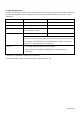
MAIN TECHNICALSPECIFICATIONS General Operating voltage 100 ~ 240 VAC Typical Power consumption 18W max Dimensions (W x H x D) 177mm x 142.07mm x 51.3mm Operating temperature range 0 – 40 °C Storage temperature range -20 – 70 °C AC adapter (or plug-in adapter) type ADAPTER 18W 12VDC/1.5A Connections DC input 12V/ 1.
Chapter 1: Connections and Setup ............................................................................................. 6 Turning on the Wireless Voice Gateway ......................................................................................... 6 Introduction ........................................................................................................................... 6 Wireless Voice Gateway Features ..................................................................................
CHAPTER 1: CONNECTIONS AND SETUP Turning on the Wireless Voice Gateway After installing the Wireless Voice Gateway and turn it on for the first time (and each time the modem is reconnected to the power), it goes through several steps before it can be used. Each of these steps is represented by a different pattern of flashing lights on the front of the modem. If there is no lighted LEDs on the front panel, check the power adapter plug-in the power jack and connect to CM correctly.
Computer Requirements For the best possible performance from your Wireless Voice Gateway, your personal computer must meet the following minimum system requirements (note that the minimum requirements may vary by cable companies): IBM PC COMPATIBLE MACINTOSH** CPU Pentium or higher. PowerPC or higher System RAM 16MB or Higher 24MB or Higher Operating System Windows* NT / 2000 / Me / XP / Vista / Windows 7, Linux Mac OS** 7.6.
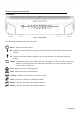
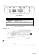
Wireless Voice Gateway Overview Front Panel Fig. 1-1 Front Panel The following illustration shows the front panel: Power - Indicates the Power status. DS - Indicates the status of Data reception by the cable modem from the Network (Downstream Traffic). US - Indicates the status of Data transmission by the cable modem to the Network (Upstream Traffic). Online - Displays the status of your cable connection.
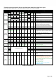
The lights on the front panel LEDs are described in the table below (from left to right): ON = the LED is light, OFF = the LED is gray, FLASH = the LED is blinking. Internet Power ON Boot-up Operation DS US Online ON ON ON ON 0.
Rear Panel Fig. 1-2 Rear Panel Connector Power Jack Phone1/ Phone2 Etherent Reset Cable Description Connector for DC12V. 2 Phone RJ11 Connectors. 2 Giga Ethernet ports, 10/100/1000 BaseT RJ-45 connector. To restart the modem or press over 5 seconds can default the modem. Connector for the cable network. Table 1-2 Rear Panel description Side Panel for WPS Fig. 1-3 Side Panel WPS – Indicates the status of the WPS functionality. WPS button: Wi-Fi Protected SetupTM.
Relationship among the Devices This illustration shows a cable company that offers DOCSIS/Euro-DOCSIS and PacketCable/EuroPacketCable compliant voice/data services. Fig. 1-5 Connection overview What the Modem Does The Wireless Voice Gateway provides high-speed Internet access as well as cost-effective, toll-quality telephone voice and fax/modem services over residential, commercial, and education subscribers on public and private networks via an existing CATV infrastructure.
The serial number The model number The Cable Modem (CM) Media Access Control (MAC) address The Terminal Adapter (EMTA) MAC address Security information: Service Set Identifier (SSID), Encryption key / passphrase (WPA2-PSK by default), channel number. Default values are indicated underneath the modem on the sticker. Please check the following with the cable company The cable service to your home supports DOCSIS/Euro-DOCSIS compliant two-way modem access. Your internet account has been set up.
Attaching the Cable TV Wire to the Wireless Voice Gateway 1. Locate the Cable TV wire. You may find it one of three ways: a. Connected directly to a TV, a Cable TV converter box, or VCR. The line will be connected to the jack, which should be labeled either IN, CABLE IN, CATV, CATV IN, etc. b. Connected to a wall-mounted cable outlet. c. Coming out from under a baseboard heater or other location. See Figure 1-6 for the wiring example.
Installation procedure for connecting to the Ethernet interface Follow these steps for proper installation. Plug the coaxial cable to the cable wall outlet and the other end to the modem’s cable connector. Note: To ensure a fast registration of the modem, the coaxial cable must be connected to the modem before it is powered on. Plug the power adapter into the socket of the cable modem and two-pin plug in the AC outlet then press the Power Switch, power on the modem.
Telephone or Fax Connection When properly connected, most telephony devices can be used with the Wireless Voice Gateway just as with a conventional telephone service. To make a normal telephone call, pick up the handset; listen for a dial tone, then dial the desired number. For services such as call waiting, use the hook switch (or FLASH button) to change calls. The following procedures describe some of the possible connection schemes for using telephony devices with the Wireless Voice Gateway. 1.
CHAPTER 2: ADDITIONAL INFORMATION Frequently Asked Questions Q. What if I don’t subscribe to cable TV? A. If cable TV is available in your area, data and voice service may be made available with or without cable TV service. Contact your local cable company for complete information on cable services, including high-speed internet access. Q. How do I get the system installed? A. Professional installation from your cable provider is strongly recommended.
technology achieves higher throughput by re-packaging data, reducing the number of overhead control packets, so that more useful data can be sent during a given amount of time. * Monthly subscription fee applies. ** Additional equipment required. Contact your Cable Company and ISP for any restrictions or additional fees.
General Troubleshooting You can correct most problems you have with your product by consulting the troubleshooting list that follows. I can’t access the internet. Check all of the connections to your Wireless Voice Gateway. Your Ethernet card may not be working. Check each product’s documentation for more information. The Network Properties of your operating system may not be installed correctly or the settings may be incorrect. Check with your ISP or cable company.
Service Information If you purchased or leased your Wireless Voice Gateway directly from your cable company, then warranty service for the Digital Cable Modem may be provided through your cable provider or its authorized representative. For information on 1) Ordering Service, 2) Obtaining Customer Support, or 3) Additional Service Information, please contact your cable company. If you purchased your Wireless Voice Gateway from a retailer, see the enclosed warranty card.
Glossary 10/100/1000 BaseT – Unshielded, twisted pair cable with an RJ-45 connector, used with Ethernet LAN (Local Area Network). “10/100/1000” indicates speed (10/100/1000 BaseT), “Base” refers to baseband technology, and “T” means twisted pair cable. Authentication - The process of verifying the identity of an entity on a network. DHCP (Dynamic Host Control Protocol) – A protocol which allows a server to dynamically assign IP addresses to workstations on the fly.
TCP/IP (Transmission Control Protocol/Internet Protocol) – A networking protocol that provides communication across interconnected networks, between computers with diverse hardware architectures and various operating systems. TFTP - Trivial File Transfer Protocol, the system by which the Media Terminal Adapter’s configuration data file is downloaded.
Federal Communication Commission Interference Statement This device complies with Part 15 of the FCC Rules. Operation is subject to the following two conditions: (1) This device may not cause harmful interference, and (2) this device must accept any interference received, including interference that may cause undesired operation. This equipment has been tested and found to comply with the limits for a Class B digital device, pursuant to Part 15 of the FCC Rules.