802.
Information in this document is subject to change without notice. No part of this document may be reproduced or transmitted in any form or by any means, electronic or mechanical, for any purpose, without the express written permission of the seller. The seller provides this documentation without warranty, term, or condition of any kind. The seller may make improvements or changes in the product(s) and/or the program(s) described in this documentation at any time.
Contents Chapter 1 Introduction................................................................................................................................................. 1 Wireless LAN Basics ................................................................................................................................................... 2 Local Area Network (LAN) .......................................................................................................................................
802.
Chapter 1 Introduction This Wireless LAN Card is an IEEE 802.11a/b dual band combo radio solution. The dual band design provides backward compatibility with 802.11b standard compliant devices and forward compatibility to new wave of 802.11a devices. Now users have the flexibility to connect to either the legacy 802.11b or higher-speed 802.11a network effortlessly. The Wireless LAN Card design is based on Atheros WLAN chipset. It supports 802.11a and 802.
802.11a/b Mini PCI Wireless LAN Card User's Manual Wireless LAN Basics This section conations some Wireless LAN basics to help you better understand how the product work together to create a wireless network. Local Area Network (LAN) Simply put, a LAN is a network that exists in a relatively limited area. A network is two or more computers connected together sharing files and peripheral devices such as printers.
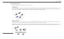
Chapter 1 Introduction Wireless Network Topologies The 802.11 standard defines two modes: Infrastructure mode and Ad Hoc mode. Ad Hoc Network An Ad Hoc network offers peer to peer connections between wireless stations that are in range of each other. The stations communicate directly with each other without using an Access Point or any connection to a wired network.
02.11a/b Mini PCI Wireless LAN Card User's Manual Roaming Between Multiple APs For large environments, multiple APs can be implemented to extend the wireless service coverage area for seamless wireless access. It allows wireless clients to roam from one AP to another while maintaining the wireless connectivity at all times. In a roaming network, all APs and wireless clients must have the same Service Set Identity (SSID) and security setting (if enabled).
Chapter 2 Installing the Driver and Utility Software This chapter describes the first-time installation for the driver and software for the Wireless LAN Card. Proper driver installation is to allow the device to operate on your host computer while the utility software, a Windows program, is to help you configure and monitor your Wireless LAN Card. Note: As this Wireless LAN Card is an embedded solution, your computer is probably shipped with its driver and software properly installed.
802.11a/b Mini PCI Wireless LAN Card User's Manual System Requirements To use the Wireless LAN Card, your computer must meet the following minimum requirements: Windows 98/Me/2000/XP 32 MB memory or greater 300 MHz processor or higher Installing Wireless LAN Driver and Software If your operation system has not been installed with the Wireless LAN Card driver, the Windows Plug-and-Play capability will automatically detect the new device (e.g.
Chapter 2 3. Select the language for this installation. 4. Click Next to continue.
802.11a/b Mini PCI Wireless LAN Card User's Manual 8 5. Click Yes to accept the license agreement. 6. Select the path to add the shortcut to and then click Next.
Chapter 2 7. Click Finish to complete the installation. Depending on your operating system, following situation may occur during the installation: • For Windows 2000: If you are prompted with one or a couple of Digital Signature not Found alarm messages, just click Yes to continue with the installation. • For Windows XP: When Found New Hardware Wizard appears, have Install the software automatically selected and follow the on-screen instructions to proceed.
Chapter 3 Station Configuration The configuration of the Wireless LAN Card is done through the Atheros Client Utility (ACU). The utility also includes a number of tools to display current statistics and status information. The Atheros Client Utility screen pops up with six available tabs: Link Status, Station Configuration, Driver Information, WLAN Status, Statistics and Tools. This chapter will focus on the Station Configuration tab to guide you through the configuration items.
802.11a/b Mini PCI Wireless LAN Card User's Manual Note to Windows XP Users Windows XP provides built-in support for wireless networks. By default, your wireless adapter is controlled by Windows XP Wireless Configuration Manager. But you can still manage your wireless adapter through the Atheros Client Utility. Configuration in either utility takes effect in another.
Chapter 3 Basic Configuration for Infrastructure Network To add a new Infrastructure configuration profile, click New on the Station Configuration tab. When the Network Configuration Settings dialog box displays, edit the General tab. The configuration items on the General tab are described as below. Configuration Name: Enter a unique name to identify this network setting. Configuration names are not case sensitive. Network Name (SSID): It is the name of the Wireless LAN group you want to participate in.
802.11a/b Mini PCI Wireless LAN Card User's Manual Figure 3-1 General Settings for Infrastructure Mode Edit the Security Tab The Atheros Client Utility provides three encryption types: Dynamic Security, Static Keys and Disable encryption. You should contact your network administrator about the encryption type. Use Dynamic Security (LEAP, 802.1X,etc.) The Atheros Client Utility supports LEAP (Cisco-EAP Wireless) and 802.
Chapter 3 Configuring the Encryption Keys To use static keys, enable the Use Static Keys option on the Security tab and click Define Static Encryption Keys to set the encryption keys. Then configure the fields below: Key Entry Method: Select the method to enter the key. If Hexadecimal is selected, only digits 0-9 and letters a-f, A-F are allowed. If ASCII Text is selected, you can enter alphanumeric characters. Key Length (bits): Defines the length for each encryption key.
802.11a/b Mini PCI Wireless LAN Card User's Manual 802.11b Preamble: The preamble is part of the IEEE 802.11b physical layer specification. All 802.11b devices are mandatory to support the long preamble format, but may optionally support the short preamble. This Wireless LAN Card supports the short preamble. The default Short & Long option allows to communicate with other 802.11b devices which support short preamble to boost the throughput. If your device is having trouble to communicate with other 802.
Chapter 3 Figure 3-3 Advanced Network Configuration Settings To Connect to an Existing Network The Athros Client Utility provides a station listing of all available APs and Ad Hoc networks on the WLAN Status tab. If a configuration profile exists for an available network, you can double-click on the network name (SSID) to connect an available network.
Chapter 4 Checking Status or Statistics The Atheros Client Utility includes a number of tools to display current statistics and status information. These tools can be accessed via the corresponding tabs of the Atheros Client Utility. This chapter will describe these tabs except the Station Configuration tab. Link Status The Link Status tab of the Atheros Client Utility contains general information about the program and its operations. The following table describes the items found on the Link Status screen.
802.11a/b Mini PCI Wireless LAN Card User's Manual Figure 3-4 Link Status 20 Screen Item Description IP Address Displays the IP address of the station.
Chapter 3 Advanced Link Status You can view advanced information about the program and its operations by clicking the Advanced button on the Link Status tab. The following table describes the items found on the Advanced Link Status screen. Screen Item Description Country The regulatory domain of the network. You can configure the country by selecting Tools > Country Select. Transmit Power Level The transmit power level. Network Name (SSID) The wireless network name.
802.11a/b Mini PCI Wireless LAN Card User's Manual Driver Information The Driver Information tab of the Atheros Client Utility contains general information about the network interface card (NIC) and the network driver interface specification (NDIS) driver. The following table describes the items found on the Driver Information screen. Screen Item Description Card Name The name of the NIC. MAC Address The station's MAC address. It is configured at the factory. Driver The location of the NDIS driver.
Chapter 3 The following table describes the items found on the WLAN Status screen. Screen Item Description Network Name (SSID) The wireless network name (service set identification). Signal Strength The received signal strength indicator. Displays the signal strength in dB. Wireless Mode Displays the wireless mode. Channel The channel the station is using. Frequency The frequency the station is using. Address (BSSID) The network AP address (basic service set identification).
802.
Chapter 3 Screen Item Description Radio Enable/Disable Enable or disable the RF Signal. Country Select Open the Country Code Selector to select the country where the Wireless LAN Card is using. Enable/Disable Tray Icon Enable or disable the tray icon.
Chapter 5 Tools Changing Display Settings To change the display settings, choose Options > Settings from the Atheros Client Utility menu. The display settings dialog box contains tools to set these parameters: Signal Strength Display Units: Sets the units used when displaying signal strength: percentage or decibels relative to one milliwatt (dBm). Refresh Interval: Sets the display refresh interval in milliseconds (ms). Data Display: Sets the display to cumulative or relative.
802.11a/b Mini PCI Wireless LAN Card User's Manual 3. Click Yes to continue. 4. The country selection takes effect immediately. Use the Atheros Client Utility to verify the selected country by looking at the Advanced information on the Link Status tab. Figure 3-11 Country Code Selector Status Monitor Tray Icon The Atheros Client Utility tray icon allows you to easily and quickly monitor your wireless connection status.
Chapter 3 Hold the mouse cursor over the tray icon to display transmit and receive speed and the current configuration profile name. Right-click on the tray icon to: Screen Item Description Launch Station Utility Launch the Atheros Client Utility. Use the Atheros Client Utility to configure the profile or view status and statistics information. Atheros Client Utility Help Launch the Atheros Client Utility Help. Enable/Disable Radio Enable or disable the RF Signal.
Chapter 4 Uninstalling the Wireless LAN Card Should you need to uninstall the Wireless LAN Card and its application software for any reason, please proceed as follows. The uninstallation procedures are the same under Windows 2000 and XP. The graphics here assume a Windows XP environment. 1. Close all programs that are currently running. 2. Double-click the Add/Remove Programs (or Add or Remove Programs for Windows XP) icon under Control Panel.
802.11a/b Mini PCI Wireless LAN Card User's Manual 32 3. Highlight IEEE 802.11a/b from the list and then click Change/Remove. 4. Select Remove and click Next.
Chapter 4 Uninstalling the Wireless LAN Card 5. When confirm message appears, click OK. 6. Click Finish and wait for the system to reboot to complete software uninstallation.
802.11a/b Mini PCI Wireless LAN Card User's Manual Federal Communication Commission Interference Statement This equipment has been tested and found to comply with the limits for a Class B digital device, pursuant to Part 15 of the FCC Rules. These limits are designed to provide reasonable protection against harmful interference in a residential installation.
Chapter 4 Uninstalling the Wireless LAN Card IMPORTANT NOTE: FCC Radiation Exposure Statement: This equipment complies with FCC radiation exposure limits set forth for an uncontrolled environment. This equipment should be installed and operated with minimum distance 20cm between the radiator & your body. This transmitter must not be co-located or operating in conjunction with any other antenna or transmitter.