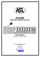
PS 6379 Mk2 SIX CHANNEL MASTER SPEAKER STATION USER MANUAL February 2013 © ASL Intercom BV DESIGNED & MANUFACTURED BY: ASL Intercom B.V. Zonnebaan 42 3542 EG Utrecht The Netherlands Tel: +31 (0)30 2411901 Fax: +31 (0)30 2667373 Email: info@asl-inter.com Web: www.asl-inter.
CONTENT OF THIS USER MANUAL 1.0 2.0 3.0 4.0 5.0 6.0 7.0 8.0 9.0 10.0 11.0 12.0 SAFETY INSTRUCTIONS .................................................................... 3 GENERAL DESCRIPTION................................................................... 4 UNPACKING ........................................................................................ 5 WARRANTY ......................................................................................... 5 INSTALLATION .....................................
1.0 SAFETY INSTRUCTIONS Please always follow these instructions to help ensure against injury to yourself and/or damage to the system Read all safety and operating instructions before you operate the apparatus. Retain all safety and operating instructions for future reference. Heed all warnings on the apparatus and in the operating instructions. Follow all installation, operating and use instructions. Unplug the apparatus from the AC power outlet before cleaning.
2.0 GENERAL DESCRIPTION The PS 6379 Mk2 is a master loudspeaker station with 6 intercom channels and a built-in power supply, offering full duplex communication with analog remote stations. The unit incorporates a loudspeaker, a gooseneck microphone and an XLR-4 headset connector. As an option, an XLR-6 headset connector can be fitted for binaural (split ear) use of the headset.
3.0 UNPACKING The shipping carton contains the PS 6379 Mk2, a power cable, 2 fuses and a 19” rack mounting kit. After unpacking the unit please inspect for any physical damage to the unit and retain shipping carton and relevant packing materials for use should the unit need returning. 4.0 WARRANTY This unit is warranted by ASL Intercom to the original end-user purchaser against defects in workmanship and materials in it’s manufacture for a period of 12 months from date of shipment to the end-user.
Switching On : To limit the inrush current after the PS 6379 Mk2 has been switched on, 30 V DC line power is provided to the intercom channels, one after the other. If a channel is found to have too many stations being connected or in case of short circuit, a circuit breaker immediately shuts off that channel from 30V DC line power. 7.0 If the total amount of to the PS 6379 Mk2 connected user stations is found to exceed the allowed maximum (see section 2.
Null Adjustment procedure, for each channel separately: • turn the ‘Own Voice” (side tone) control knob to minimum • set Null Adjust trimmers in start position: fully clockwise.
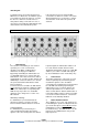
9 AUX Volume knob By turning this knob one adjusts the level of the auxiliary signal as sent to the corresponding channel. The AUX signal may originate from either AUX input 1, AUX input 2 or AUX input 3 (see AUX inputs #34 and AUX select switches #35) 10 SYSTEM LINK LED This yellow LED illuminates if a channel of another ASL Intercom System has been connected to the PS 6379 Mk2 through the “System Link” connector (#33) of the corresponding channel.
15 MASTER VOLUME knob By turning this knob one adjusts the volume of the sum of all intercom signals as heard in the loudspeaker and/or headset. This knob may also adjust the master volume control for both the intercom and the PGM (Program Audio) signals, depending on the position of jumpers #44. 16 PGM VOLUME By turning this knob one adjusts the listen volume of the PGM input.
21 SPEAKER ATTENUATOR trimmer This trimmer adjusts the extent to which the loudspeaker is automatically dimmed when the gooseneck microphone is switched on. It prevents unit feedback if Null Adjust is not sufficient. It also minimizes system feedback or a 'hollow' sound when the gooseneck microphones of other speaker stations (on one or several of the connected party lines) are switched on as well.
Headset connector pin assignments : 1. Shield mic. (GND) 2. mic. + 3. phones + 4. phones When connecting a headset, speaker and gooseneck microphone are disabled automatically. The speaker can be enabled again by pushing the SPEAKER on/off button (#18). The PS 6379 Mk2 can optionally be equipped with an XLR-5 headset connector for binaural use of the headset.
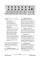
36 IFB mode switches E and F To (independently ) put channel E and F into IFB mode 37 PGM INPUT connector + ground lift This XLR-3 female connector is an electronically balanced input for line level audio signals. The input is for receiving a program (PGM) audio signal, which is routed to the loudspeaker and the headset connector only. The PGM volume can be adjusted by knob #16.
9.0 INTERNAL CONTROLS 43 Binaural Jumper Settings The PS 6379 Mk2 can optionally be equipped with an XLR-5 headset connector for binaural use. In that case the position of jumpers determine - for each channel separately - the routing of the audio to the headset cans: either to the left can, or to the right can, or to both cans or not to any can.
45 HEADSET MIC GAIN trimmer With this trimmer the gain of the headset microphone can be adjusted (factory set for a dynamic headset microphone). 10.0 46 GOOSENECK MIC GAIN trimmer With this controls the gain of the gooseneck microphone can be adjusted (factory set for the electret gooseneck microphone). IFB FUNCTION With the IFB Mode switches #36 on the rear panel, channel E respectively channel F can be put into IFB Mode, which is indicated on the front panel by lit IFB Mode LED indicators.
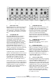
11.0 DIP SWITCHES Inside the PS 6379 Mk2 the following DIP switches are to be found: DIP switch A IFB and TALK If this DIP switch is in ‘OFF’ position (= factory setting) and the Talk button of an IFB channel is pushed and held, the microphone signal is not sent to the intercom channels. In the ‘ON’ position and the TALK button of an IFB channel is pushed and held, the microphone signal is also sent to all intercom channels of which the Talk LED is lit.
12.0 TECHNICAL SPECIFICATIONS Intercom System dynamic range: 80 dB frequency response : 200 Hz – 15 kHz (-3 dB) call send signal: +2.8 mA call signal threshold (receive): +2.4 V DC supply voltage: +30 V DC (12 - 32 V DC) power interrupt time (mic mute): 0.1 sec line Impedance: 390 Ω (1kHz), 2.2 kΩ (DC) audio level: nom. -18 dBu, max. +4 dBu Null Adjust Rejection: 0 - 30dB adjustable @ 1 kHz Switch Mode Power Supply module mains voltage : 100 – 240 V AC, 50/60 Hz output voltage: +30 V DC (+/- 5%) max.