PS 630 SIX CHANNEL REMOTE SPEAKER STATION USER MANUAL October 2013 This product is designed and manufactured by: ASL Intercom BV Zonnebaan 42 3542 EG Utrecht The Netherlands Phone: +31 (0)30 2411901 Fax: +31 (0)30 2667373 E-mail: info@asl-inter.com Web: www.asl-inter.
CONTENT OF THIS USER MANUAL 1.0 2.0 3.0 4.0 5.0 6.0 7.0 8.0 9.0 10.0 11.0 INTRODUCTION .................................................................................... 3 INSTALLATION ...................................................................................... 3 FRONT PANEL CONTROLS & CONNECTOR ...................................... 3 REAR PANEL CONNECTORS............................................................... 6 INTERNAL CONTROLS ........................................................
1.0 INTRODUCTION The PS 630 is a six channel remote speaker station designed for use in an ASL Intercom system. It incorporates a loudspeaker, a gooseneck mic and a headset connector and provides full duplex communications. The PS 630 RM model has, instead of a gooseneck mic, a built-in electret microphone. Each channel has a Volume (listen level) control, a TALK and CALL button with LED indicators and a two-stage side tone trimmer. A master volume knob controls the speaker/headset volume.
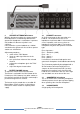
1 LISTEN LEVEL control knobs To preset the listen level for each intercom channel. By turning the knob fully counter clockwise, the channel is switched off. See #17 for receiving a Call signal whilst the channel is switched off 4 MASTER VOLUME knob This knob is a master volume control of the listen levels of the 6 intercom channels (see also #1), for both the speaker and the headset. 2 TALK buttons These buttons allow talking to each channel separately or to several channels simultaneously.
8 SPEAKER ATTENUATOR trimmer With this trimmer one adjusts the extent to which the loudspeaker is automatically dimmed if the gooseneck microphone is switched on. It prevents unit feedback if side tone rejection is not sufficient. It also minimizes system feedback or a 'hollow' sound when the gooseneck mics of other speaker stations are switched on.
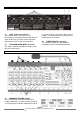
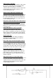
4.0 REAR PANEL CONNECTORS 13 LINE connectors (A thru F) These twelve XLR-3 connectors are for connecting the PS 630 to the intercom party lines. Each channel has an XLR-3 female connector (input) and an XLR-3 male connector (link). 14 PROGRAM AUDIO INPUT connector This input is electronically balanced and accepts line level audio signals. In case of binaural use of the PS 630, internal jumpers (see #18) determine the routing of the PGM signal to the headset.
17 CALL RECEIVE jumpers For each channel separately, these jumpers enable or disable the reception of a CALL signal when the channel is switched off. 18 PGM ROUTING jumpers With these two jumpers one determines whether the PGM (program audio) listen level is also controlled by the Master Volume knob (see #4) and – in case of binaural use of the PS 630 - the routing of the PGM signal to the headset. 19 HEADSET MIC GAIN To adjust the gain of the headset microphone.
Buzzer max. SPL: 85 dBA Speaker Driver Amp max. output power: 1.6 Wrms @ 16 Ω Program Audio Input input impedance: 28 kΩ (balanced) nominal input level: 0 dBU max. input level: +15 dBu Direct Mic Output output impedance: 50 Ω (balanced) nominal Output Level: + 6 dBu max. Output Level: +21 dBu Power Consumption PS 630 current (at 30 V DC): 105 mA quiescent, 140 mA signaling 280 mA at max.
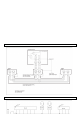
Cable screens to XLR pin 1 The screen of each separate microphone cable and/or the screen of each single pair in a multi-pair cable, should be connected to pin 1 of each XLR-3 connector. Do not connect these screens to the metal housing of ASL unitst or XLR-3 wall boxes. See section ‘Earthing Concept’.
.0 EARTHING CONCEPT 11.