
User manual

PAGE 5
User Manual PS 430 / October 2013 © ASL Intercom BV
.
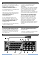
8 BUZZER VOLUME trimmer
This trimmer adjusts the volume of the buzzer,
which is located behind the front panel. The
buzzer is activated if the CALL button of the PS
430 (or a CALL button of any other station on the
party lines to which the PS 430 is connected) is
pushed for longer than 2 seconds, provided there
is no Buzzer Mute Signal on these party lines
coming from a Pro Series master station or
separate power supply.
9 HEADSET connector
This is an XLR-4 connector for the connection of
a local headset if private conversation is desired.
The headset must have a can impedance of
minimum 200 ohms. In case the headset has two
cans in parallel, each can must have an
impedance of minimum 400 ohms.
The headset microphone may be of the dynamic
or electret type
Pin assignments headset connector :
Pin 1. Shield Mic. (GND)
Pin 2. mic. +
Pin 3. phones +
Pin 4.. phones -
If a headset is connected, loudspeaker and
gooseneck microphone are disabled
automatically.
10 GOOSENECK microphone
This a noise canceling microphone. A limiter
prevents the mic pre-amp from clipping when
speaking close in the microphone. The
gooseneck mic. is automatically disabled if a
headset is connected to the PS 430.
11 LOUDSPEAKER
This is a high quality 16 Ω loudspeaker. The
speaker is automatically disabled if a headset is
connected to the PS 430.
4.0 SIDE PANEL CONNECTORS
12 LINE connector for channel A & B
13 LINE connector for channel C & D
These two XLR-5 connectors are for connecting
the PS 430 to the intercom system party lines.
One connector is for channels A and B, one
connector for channel C and D.
For linking the XLR-5 sockets to XLR-3 intercom
line connectors, each PS 430 comes with two
Y-cords, having an XLR-5 connector at one end
and two XLR-3 connectors at the other end.
On the Y-cords, the XLR-3 with the white ring
corresponds with channel A or C.
Pin assignment XLR-5 connector #12
1. 0 V / ground shield A+B
2. +30 V power wire channel A
3. audio wire channel A
4. +30 V audio wire channel B
5. audio wire channel B
Pin assignment XLR-5 connector #13
1. 0 V / ground shield C+D
2. +30 V power wire channel C
3. audio wire channel C
4. +30 V audio wire channel D
5. audio wire channel D
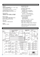
5.0 INTERNAL CONTROLS
MIC GAIN trimmers
Inside the unit there are two trimmers to adjust
the mic gain of the gooseneck microphone and
the headset microphone separately.
They are located on a PC board.
They can be reached as follows :
o remove the screws of the bottom plate
o slide the plate to one side and take it out
o take away the plastic isolation plate
The trimmers are labeled ‘GOOSE’ for the
gooseneck microphone and ‘HEADS’ for the
headset microphone