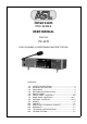
PRO SERIES USER MANUAL FOR THE PS 4379 FOUR CHANNEL LOUDSPEAKER MASTER STATION CONTENTS 1.0 2.0 3.0 4.0 5.0 6.0 7.0 8.0 9.0 10.0 11.0 12.0 13.0 14.0 SAFETY INSTRUCTIONS…………………………….….......3 GENERAL DESCRIPTION ..............................................4 UNPACKING .....................................................................4 MECHANICAL INSTALLATION...........................................4 MAINS POWER...................................................................5 FRONT PANEL CONTROLS.
User Manual PS 4379 - Issue 1 © 2007 ASL Intercom, Utrecht, The Netherlands
1.0 IMPORTANT SAFETY INSTRUCTIONS ! Please always follow these instructions to help ensure against injury to yourself and damage to the system. 1) Read all safety and operatinginstructions before you operate the apparatus. 2) Retain all safety and operating instructions for future reference. 3) Heed all warnings on the apparatus and in the safety and operating instructions. 4) Follow all installation, operating and use instructions.
2.0 GENERAL DESCRIPTION The PS 4379 is designed to be a four channel loudspeaker master unit in an ASL Intercom system and can be used in portable as well as fixed applications. It incorporates a power supply, auxiliary inputs, program input, headset connector, loudspeaker and a gooseneck microphone, stage announce output, IFB Mode, Paging Mode, Near Station Mode and Extended Mode (see section 9 for further explanation of each Mode) and provides full duplex communications within an ASL intercom system.
.0 MAINS POWER The PS 4379 may be connected to the mains power outlet to which other audio equipment is connected. The outlet should have a clean earth. Avoid using mains power outlets, which also power dimmer controlled lighting equipment. Before connecting the unit to its AC power source, check if the mains voltage of the unit (100 V - 240 V) is in accordance with your local mains voltage.
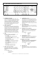
.0 FRONT PANEL CONTROLS & CONNECTOR 1 LISTEN LEVEL control knobs These knobs preset the listen level for each channel separately. 2 TALK buttons These buttons allow you to talk to each channel separately or simultaneously. The large green LED is lit when the talk function for that channel is activated.
6.0 FRONT PANEL CONTROLS & CONNECTOR continued 8 SPEAKER ON/OFF With this button the speaker can be switched on or off. The LED within the button will light up if the speaker is switched on. If the speaker has been switched on when a headset was connected, the speaker will automatically switch off. By pushing the speaker on/off button, the speaker will switch back on and the audio can be heard over both the speaker and the headset.
6.0 FRONT PANEL CONTROLS & CONNECTOR continued 14 HEADSET connector A XLR-4 type connector for the connection of a local headset when private conversation is desired. The headset must have a can impedance of 200 ohms (or greater), or each a minimum of 400 ohm when in parallel. The headset microphone may be of the dyna mic or electret type. Pin assignments : 1. Shield mic. (GND) 2. mic. + 3. phones + 4. phones When connecting a headset, speaker and gooseneck microphone will be switched off automatically.
6.0 FRONT PANEL CONTROLS & CONNECTOR continued 22 SET UP LOCK The setup of the AUX, IFB and Buzzer mutes can be locked by pushing a small pin into the SETUP lock. It will be unlocked by pushing it again. When pushing and holding the set up lock, the light intensity of the LEDs of the MIC MUTE-, BUZZER MUTE-, AUX- and IFB LEDs, can be increased by turning the AUX level / IFB Dim knob. In "Near Station" mode (see section 9.
7.0 REAR PANEL CONTROLS & CONNECTOR 28 EXTENDED STATION LINK This connector is used when 2 units (either 2 x PS 4379 or 1 x PS 4379 with PS 4379) should be linked to form a 10 or 12 channel unit. When linked, 1 station will be the master with an active speaker and gooseneck /electret microphone. The speaker and microphone of the other unit will be switched off. The CALL ALL and TALK ALL signals will also be sent to the channels of the extended unit.
7.0 REAR PANEL CONTROLS & CONNECTOR continued 38 STAGE ANNOUNCE OUT This XLR 3 male connector is electronically balanced and outputs the pre-amplified microphone signal at line level when the STAGE ANNOUNCE button is used. 39 EXT. SPEAKER An external speaker can be connected to this 6,3 mm Jack. In this case the internal speaker switches off and the audio is sent to the external speaker.
No. 5 12 RESERVED 1 TALK Momentary Ch. A RESERVED 2 TALK Momentary Ch. B PAGING Channel A TALK Momentary Ch. C PAGING Channel B Dip D 4 3 TALK Momentary Ch. D 5 IFB and TALK (factory setting = 'off') If this dip switch is in 'on' position, and one presses and holds the TALK button of the IFB Channel, the microphone signal will also be sent to all intercom channels of which the TALK LED is lit. (For IFB functions see section 9.
8.0 INTERNAL CONTROLS / DIP SWITCHES DIP SWITCH BLOCK C DIP SWITCH BLOCK F No. 6 No. 5 No. 4 No. 6 No. 3 No. 2 No. 1 RESERVED (factory setting = 'off') RESERVED (factory setting = 'off') PAGING Channel D (factory setting = 'off') If this dip switch is in 'on' position, the corresponding channel will be set to PAGING mode. (For PAGING functions see point 9.0 MODES) PAGING Channel C (factory setting = 'off') (Same as for No. 4) PAGING Channel B (factory setting = 'off') (Same as for No.
8.0 INTERNAL CONTROLS continued Inside the unit there are several controls that can be adjusted. These internal controls are located on the main PC board. 43 14 BINAURAL JUMPER SETTING For each channel separately, these jumpers determine how the audio of that channel can be heard in case of binaural use. 44 PGM ROUTING JUMPERS With these two jumpers you can determine, for binaural applications, how the PGM signal is controlled and where it is to be sent to.
9.0 MODES IFB Mode This mode is used for one way 1 to 1 communication, e.g. director to talent. The talent will constantly listen to the IFB Aux signal or the AUX signal if the corresponding dip switch is in 'off' position (see point 8 internal controls / dip switches). The director can talk over the Aux signal by pushing and holding the IFB TALK button. The AUX volume will be dimmed to a set IFB dim factor and the microphone signal will be added to the IFB line.
10.0 CABLING For the PRO Series Intercom system the interconnecting cables are of the shielded two-conductor microphone cable type and the intercom line connectors are of the XLR-3 type. Audio and Call signals are on XLR pin 3, DC power is on XLR pin 2. XLR pin 1 is connected to the shield of the cable which functions as the common return for audio and power. Since the audio signal is transferred in an unbalanced * way, certain rules have to be obeyed when installing the cables of an intercom network.
11.0 PARTY LINE, TECHNICAL CONCEPT ASL's PRO Series offers a complete two way ('full duplex') communications system. Users of the system are connected via a 'party line'. Master stations (with built-in power supply), beltpacks, speaker stations and power supplies are interconnected via standard microphone cable. One wire is used as an audio line, one as a power line and the screen of the cable functions as earth/return. Current drive is used for signal transfer.
14.0 DESIGN CRITERIA Applications / Environment of use ASL Pro Series equipment is designed for use as a wired communications system in theatres, in Radio/TV production facilities, in factories, and in utilities com plexes such as airports, railway stations and coach terminals. ASL equipment can be used outdoors in normal weather conditions. In conditions with excessive cold (<-10° C), heat (>50° C) or humidity (>85%), ASL equipment might not perform properly.
User Manual PS 4379 - Issue 1 © 2007 ASL Intercom, Utrecht, The Netherlands 19
User Manual PS 4379 - Issue 1 © 2007 ASL Intercom, Utrecht, The Netherlands
User Manual PS 4379 - Issue 1 © 2007 ASL Intercom, Utrecht, The Netherlands
User Manual PS 4379 - Issue 1 © 2007 ASL Intercom, Utrecht, The Netherlands