PS 680 SIX CHANNEL POWER SUPPLY WITH AUX MATRIX USER MANUAL October 2013 This product is designed and manufactured by: ASL Intercom B.V. Zonnebaan 42 3542 EG Utrecht The Netherlands Phone: +31 (0)30 2411901 Fax: + 31 (0)30 2667373 E-mail: info@asl-inter.com Web: www.asl-inter.
CONTENT OF THIS USER MANUAL 1.0 SAFETY INSTRUCTIONS .......................................................... 3 2.0 GENERAL DESCRIPTION PS 680 ............................................ 4 3.0 MECHANICAL INSTALLATION ................................................. 4 5.0 FRONT PANEL CONTROLS ..................................................... 5 6.0 REAR PANEL CONTROLS & CONNECTORS.......................... 5 7.0 TECHNICAL SPECIFICATIONS PS 680 ................................... 6 8.
1.0 SAFETY INSTRUCTIONS Please always follow these instructions to help ensure against injury to yourself and/or damage to the system 1. Read all safety and operating instructions before you operate the apparatus. 2. Retain all safety and operating instructions for future reference. 3. Heed all warnings on the apparatus and in the safety and operating instructions and follow all installation and use instructions. 4. Follow all installation, operating and use instructions 5.
2.0 GENERAL DESCRIPTION PS 680 The PS 680 (19”/1RU) is designed to be a six channel power supply in an ASL intercom system. The unit is connected to the party lines with standard microphone cables (2 wires + 1 shield) Inside the unit are 2 switch mode power supply modules, which are fully protected and can together drive at least 20 Pro Series beltpacks or 10 Pro Series 2-ch speaker stations (or a combination), operating at full power.
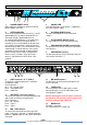
.0 FRONT PANEL CONTROLS 1 POWER ON/OFF switch Mains power push button to switch the internal power supplies On or Off 3 POWER LED This LED illuminates if line power is supplied by the internal power supply 2 OVERLOAD LEDs There is an overload LED for channel A, C and E (powered by PSU 1) and an overload LED for channel B, D and F (powered by PSU 2). An overload LED illuminates if a circuit breaker has shut off the 30V DC line power due to overload.
14 REMOTE MUTE CONTROL + AUX OUTPUTS connector The Mic Mute and Buzzer Mute push buttons on the PS 680 allow for sending these mute signals to all channels simultaneously. In case it is required that these mute signals can also be sent to each channel separately, an external switch box is needed, to be connected to this D25 connector. To activate a mic of buzzer mute, the switch box connects the referring pins of the D-25 connector to ground. See D-25 pin layout. The external switch box is made to order.
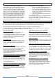
8.0 PARTY LINE, TECHNICAL CONCEPT User stations in an ASL intercom system are connected via one or several 'party lines'. A party line offers two way (‘full duplex’) communication and consists of standard microphone (multi-pair) cable. One wire is used as an audio line, one as a power line and the screen of the cable functions as earth/return. Current drive is used for signal transfer.
10.0 11.