PlugLink-ETH-500 User’s Guide PL9670-Q2 QUICKFIND LOCATOR Contact Information Getting Help Table of Contents Installation 66-0376-01Rev.
© 2012 Asoka USA Corporation ALL RIGHTS RESERVED Notice: No part of this publication may be reproduced or transmitted in any form or by any means, electronic or mechanical, including photocopying and recording, or stored in a database or retrieval system for any purpose without the express written permission of Asoka USA Corporation. Asoka USA Corporation reserves the right to make changes to this user’s guide at any time without notice and assumes no responsibility for its use.
Contact Information For more information about the PlugLink-ETH-500 or any of Asoka’s other leading-edge solutions, please contact us using any of the following methods: z Voice calls: We welcome your calls Monday through Friday, from 9:00 am to 5:00 pm Pacific Time at (408) 550-8167. Voice mail is available during non-business hours. z Email: If you prefer, you can send information requests to our e-mail address: sales@asokatech.com.
Table of Contents 1 Simple Installation ...................................................................... 5 Package Contents................................................................................................... 5 Types of Connections ............................................................................................. 5 Simple Connection (Peer to Peer) ............................................................................ 6 Simple Broadband Connection ........................
Simple Installation Congratulations on your purchase of the PlugLink-ETH-500 ! This adapter allows you to network your home or office by plugging directly into an electrical outlet. With your PlugLink-ETH-500, you can easily share your high-speed Internet, mp3s, video, and gaming throughout the home or office. This manual describes how to connect your PlugLink-ETH-500 to a PC or cable/DSL Router.
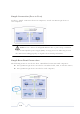
Simple Connection (Peer to Peer) To share a simple connection between computers, attach one PL9670-Q2 device to each computer. NOTE: Do not connect the PlugLink-ETH-500 into a power strip, extension cord, un-interruptible power supply (UPS), or surge protector. This may prevent the unit from working properly or degrade the network performance.
Other Connections You can also use the PlugLink-ETH-500 with other Ethernet enabled devices, such as IP Cameras, IP set top box, game consoles, etc. “Up to eight (8) PL9672 can be placed on the same PLC (Powerline Communication) network.” Finding a Suitable Location Find a suitable location to install your PlugLink-ETH-500 . Where you install the units can affect their performance. Find a location that is: z z z Acceptable temperature and humidity ranges.
Advanced Configuration (Expert Users Only) This chapter provides information on installing and setting up the PlugLink-ETH-500. NOTE: Do not connect the PlugLink-ETH-500 into a power strip, extension cord, un-interruptible power supply (UPS), or surge protector. This may prevent the unit from working properly or degrade the network performance. Installing the Software Following are software installation procedures for advanced users. NOTE: Software installation is not required for normal use.
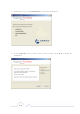
3. In the Start screen, click Install Driver to start the installation. 4. In the Welcome screen of the screen of the wizard, click Next to begin the installation.
5. Read the End User Software License Agreement, and if you agree, click the Agree button to continue the installation. 6. To change the name of the PlugLink AV unit, select Yes, and enter a name in the text field. Otherwise, select No. Click Next to advance to the next screen.
7. Select the location where you want to install the drivers and software and click the Install button. 8. When the installation of the PlugLink drivers and software is complete, you can use Power Manager Utility for advanced configuration of your PL9672 unit. Click Finish to finish the installation wizard.
Network Management The PlugLink Power Manager utility software allows you to manually configure a PlugLink HD AV Adapter that is directly connected to your Personal Computer or to any PlugLink Adapters that are remotely residing on your PlugLink Home network. NOTE: The Power Manager Utility software is for all Asoka PlugLink devices.
Profile Screen Changing your device Name and Network Encryption Key (NEK) Use the Device(s) Screen to change your local and remote device name, also to change your local and remote device Network Encryption Key (NEK) (also known as the Network Password).
DEVICE NAME Changing your local device name: 1. Connect your PlugLink adapter to your PC. For instructions on how to connect your PlugLink to your PC, please refer to page 7 (Installing the Hardware). 2. Run the PlugLink Power Manager software. If you have not installed the PlugLink Power Manager software onto a PC, please refer to page 8 (Installing the Software). 3. From the Power Manager main menu, click “Device(s)”. 4.
Changing your remote device name: 1. Connect your PC to one of your PlugLink adapters. For instructions on how to connect your PlugLink to your PC, please refer to page 7 (Installing the Hardware). 2. Run the PlugLink Power Manager software. If you have not installed the PlugLink Power Manager software onto a PC, please refer to page 8 (Installing the Software). 3. From the Power Manager main menu, click “Device(s)”. 4. A list of PlugLink devices will appear on the left side of your Power Manager screen.
DEVICE NETWORK ENCRYPTION KEY (NEK) Understanding the Network Encryption Key: The Network Encryption Key (NEK) is similar to a domain name or work group. Only those devices encrypted with the same domain name or work group, will have access to your Powerline Network. All Asoka PlugLink adapters are encrypted with the same default Network Encryption Key. The default Network Encryption Key is: HomePlugAV.
5. Select your local device, by clicking on the first device MAC Address from the list. Make sure that the device selected is highlighted in yellow. IMPORTANT: You must check the box to the left of the Device Name. 6. Enter the new Network Encryption Key (NEK) in the New Network Password field. The new Network Password must be at least 8 characters long and can not have spaces. 7. Click “Update” to update the new Network Password. 8.
Changing your remote device Network Encryption Key (NEK): WARNING: If you change your remote device Network Encryption Key (Network Password) your remote device will no longer be able to communicated with all your other PlugLink adapters. You must change the Network encryption key on all your PlugLink adapters to the new Network Encryption Key in order for them to communicate. NOTE: When changing your remote device NEK, you will be prompted to enter the selected device 16-digit Password at least once.
8. If the new Network Password was accepted, the message “Network Encryption Key is successfully changed. The utility will now scan the Powerline network” will appear. 9. Congratulations, you have successfully changed your local device Network Password.
Resetting and Upgrading the PlugLink-ETH-500 Run the PlugLink Power Manager and use the Upgrade screen to: z z z Reset your PlugLink-ETH-500 to Factory Defaults Reset (Reboot) your PlugLink-ETH-500 Upgrade the Firmware How to reset your PlugLink-ETH-500 to its Factory Defaults, reboot and Upgrade the firmware. 1. Connect your PC to one of your PlugLink adapters. For instructions on how to connect your PlugLink to your PC, please refer to page 7 (Installing the Hardware). 2.
Prioritizing the Network Traffic Use the QoS screen to prioritize your traffic through the device. QoS requirements are different for various data types such as streaming video or music, voice and raw data. To provide higher QoS for streaming data, priority levels can be set using tags at the beginning of data frames. The QoS level settings are: CAP3: Highest CAP2: Medium and CAP1: Lowest.
Viewing the Network Statistics screen The Statistics screen shows information on HomePlug packets that are transmitted and received by the devices in your network. To enable this function, click Enable Statistics. The value shown by the Power Manager is a cumulative total of the packet data that was collected from the start of the “Enabled Statistics” button. Statistics screen Viewing the Link screen The Link Screen has two sub-screens that provide information about your Ethernet and HomePlug connection.
Link Screen; Ethernet Sub-Screen Statistics Sub Screen: Use the Statistics sub screen to view statistical information about your connection between a source device and a specific destination device in your network. Click the Retrieve button to start accumulating the statistical information.
Viewing the LED screen This is the LED Manager tab. It allows you to configure the LED functionality threshold. IMPORTANT: YOU CAN ONLY ENTER WHOLE NUMBERS DIVISIBLE BY 4. Example: 100, 80, 60 (no odd numbers) etc. If you enter a value that is not divisible by 4; then you will get the message: “The value Yellow or Green must divide by 4!” LED screen Rescanning your Powerline Network Use the Rescan button to scan for your Powerline devices under the same Network Password in your HomePlug network.
Manually Resetting the Firmware and Network ID (NID) You can use the buttons on your PlugLink device to reset the firmware back to its factory defaults, and to create or associate your PlugLink-ETH-500 to a randomized Powerline Network. For details on how to use the buttons on your PlugLink adapter, please refer to page 32 of this manual. Note: The PlugLink device must be plugged into an electrical outlet when using these buttons.
Troubleshooting Following are solutions to a few situations you might encounter. If you do not find a solution in this chapter, contact Asoka USA Technical Support by phone at (408) 5508173 or through email at support@asokatech.com. Symptom: I can't connect to anything and there are no lights activated on my PL9670Q2. Solution: Unplug the device from the electrical outlet in question. Locate another available outlet in your home.
Solution #2: The Network Encryption Key (NEK) may not be correct on your devices. Reset the Network Encryption Key using the Factory Reset button located on the bottom of your PL9670-Q2 device. This will reset the NEK back to the default of HomePlug. Test your connection again. If this still does not work, perform the factory reset on all of your other PL9670-Q2 devices in your network. Solution #3: It is possible some outlets in your home are not connect together.
Specifications This appendix lists the specifications for your PL9670-Q2. Standards Compliance: •HomePlug® AV • IEEE 802.3, IEEE 802.3x, IEEE 802.
Environmental • Operating temperature: 32°F to 113°F (0°C to 45°C) • Operating Specifications: humidity: 10% to 85% Non-condensing • Storage temperature: -4°F to 158°F (-20°C to 70°C) • Storage humidity: 5% to 90% Non-condensing Quality of Service: •ToS • 802.
Components Front Panel Use the status lights on the front panel to verify connections.
The following table describes the status light functions in the front panel: Status Light State Indication Illuminated Device is powered on Off Devices has no power Red and Green illuminate alternately Stand by mode (After 3 minutes no link) Blinking Red low connection Blinking Yellow good connection Blinking Green excellent connection Off no connection Illuminated Ethernet connectivity Blinking Ethernet traffic Off No Ethernet connectivity Power PLC Activity Eth Link Bottom Panel
Note: Write this information down in your Warranty Support Information card for future reference. Buttons The PlugLink-ETH-500 device has two hardware push buttons: FW RST (Firmware Default Reset ) button – Resets the PlugLink-ETH-500 back to factory default settings. Press and hold the button with a pin or sharp object for about 2 seconds until you see the lights on the device flash briefly.
IMPORTANT: If the power light is not blinking green, repeat Step “a” until the power light is blinking green. In about 15 seconds the POWER light will change from flashing green to solid green and the PLC ACT (Power line Communication Activity) light will turn solid green (flashing green when there is data traffic) indicating they are synchronized with the same NEK.
Warranty Asoka warrants that (a) the hardware components of the product will be free from defects in materials and workmanship under normal use from the date of purchase when used within the limits set forth in the Specifications section of the User Guide, and (b) the software components will perform substantially in accordance with Asoka's published specifications for ninety (90) days from the date of purchase, but does not warrant that the software will be error-free or free of all defects.
product covered by the warranty. Prior to returning any defective product, the purchaser or the authorized merchant from whom the purchaser originally bought the product must obtain a Return Material Authorization (RMA) number from Asoka. All defective products should be returned to Asoka with shipping charges prepaid. Asoka will not accept collect shipments.
FCC Notice FCC Statement This equipment has been tested and found to comply with the limits for a Class B digital device, pursuant to part 15 of FCC Rules. These limits are designed to provide reasonable protection against harmful interference in a residential installation. This equipment generates and can radiate radio frequency energy and, if not installed and used in accordance with the instructions, may cause harmful interference to radio communications.
Note: The manufacturer is not responsible for any radio or TV interference caused by unauthorized modifications to this equipment. such modifications could void the user’s authority to operate this equipment.
Asoka USA Corporation 2620 Augustine Drive Suite 230 230 Santa Clara, California 95054 USA Phone: (408) 550–8167 Fax: (408) 884–2390 www.asokatech.com 66-0376-01Rev.