Asoka® User’s Guide PlugLink® 9850 IP Camera PL9850-CMS User’s Guide PlugLink 9850 IP Camera PL9850-CMS © 2007 Asoka USA Corporation. Asoka, PlugLink and the Asoka logo are registered trademarks or trademarks of Asoka USA Corporation. Information is subject to change without notice. All rights reserved.
Asoka® User’s Guide PlugLink® 9850 IP Camera PL9850-CMS Table of Contents Chapter Title Page 1 Introduction 3 2 Important Safety Information 4 3 Learning About your PlugLink IP Camera 5 4 Connecting the PlugLink 9850 for Setup 11 5 Installing and Configuring the PlugLink IP Camera 12 6 Placement Options 20 7 Using the PlugLink 9850 IP Camera Utility 21 8 Using the PlugLink 9850 Web based Utility 27 9 Configuring the PlugLink 9850 for Remote Access 32 10 Technical Support Info
Asoka® User’s Guide PlugLink® 9850 IP Camera PL9850-CMS Chapter 1 Introduction Thank you for purchasing a PlugLink 9850 IP Camera (PL9850-CMS) from Asoka. The PlugLink 9850 combines the functionality of a traditional IP Camera with the flexibility of using the existing home wiring. Based on the HomePlug 1.0/Turbo standards, the PlugLink 9850 provides surveillance and monitoring capabilities to your existing power line network in your home or office.
Asoka® User’s Guide PlugLink® 9850 IP Camera PL9850-CMS Chapter 2 Important Safety Information The following precautions should be taken when using this product: Read all instructions before installing and operating this product. Keep these instructions in a safe and handy place for future reference. Heed all warnings. Follow all instructions. Do not install near any heat sources such as radiators, heat registers, stoves, or other devices (including amplifiers) that produce heat.
Asoka® User’s Guide PlugLink® 9850 IP Camera PL9850-CMS Chapter 3 Learning about your PlugLink 9850 IP Camera Package Contents PlugLink 9850 IP Camera (PL9850-CMS) AC/DC power adapter 3-foot Ethernet Cable Wall Mounting Brackets Installation Resource CD Quick Installation Guide Warranty and Support Information Card If any of the parts are incorrect, missing, or damaged, contact the retailer where you made your purchase.
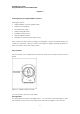
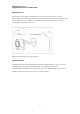
Asoka® User’s Guide PlugLink® 9850 IP Camera PL9850-CMS Table 3-1: Status Light Descriptions Green Solid Indicates camera initialization Orange Solid Indicates camera is ready Green Blinking Indicates Ethernet connectivity Figure 3-2: PL9850-CMS Right Side Panel The Rear Panel The rear panel features two ports: POWER The POWER port is where you will connect the power adapter. ETHERNET The ETHERNET port is where you will connect the Ethernet network cable.
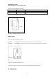
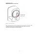
Asoka® User’s Guide PlugLink® 9850 IP Camera PL9850-CMS Unique device password Device MAC address IP address Serial number Note: For future convenience, please write this information down on your Warranty Support Information card. Figure 3-4: Product label The Bottom Panel The bottom panel contains another mounting bracket and a RESET button. The RESET button is what you will press if you need to reset the camera.
Asoka® User’s Guide PlugLink® 9850 IP Camera PL9850-CMS Figure 3-5: Bottom panel of the PL9850-CMS.
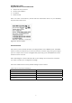
Asoka® User’s Guide PlugLink® 9850 IP Camera PL9850-CMS Mounting Bracket The camera can stand on a flat surface on its own or be mounted on a wall. Depending on the positioning you want, you can attach the camera head to its stand at two different points. Please see Chapter 4: “Placement Options” for more on mounting your camera to the wall.
Asoka® User’s Guide PlugLink® 9850 IP Camera PL9850-CMS Figure 3-7: Pan/Tilt Camera Note: Pan/Tilt operation must be controlled only by pressing the control buttons. Do not apply external pressure to the pan/tilt portion of the camera. Any forced movement can damage the internal mechanism.
Asoka® User’s Guide PlugLink® 9850 IP Camera PL9850-CMS Chapter 4 Connecting the PlugLink 9850 IP Camera for Setup Before connecting your PlugLink 9850 to your wired network, please connect it directly to your computer with an Ethernet cable. Connection to a Wired Network for Setup 1. Connect the power supply into a nearby wall outlet. 2. Connect the enclosed Ethernet cable to the Ethernet port of the unit. 3. Connect the other end of the Ethernet cable to the Ethernet port of the PC. 4. Turn on PC.
Asoka® User’s Guide PlugLink® 9850 IP Camera PL9850-CMS Chapter 5 Installing and Configuring the PlugLink 9850 IP Camera Note: Do not connect the power supply of the PlugLink 9850 IP Camera into a power strip, extension cord, uninterruptible power supply (UPS), or surge protector. This may prevent the unit from working properly or degrade the performance of your camera. 1. Insert the enclosed Installation Resource CD into your CD-ROM drive. The Installation Utility should appear automatically.
Asoka® User’s Guide PlugLink® 9850 IP Camera PL9850-CMS Figure 5-2: Beginning the Installation Process 5. Please read the license agreement carefully and click on the Agree button to continue.
Asoka® User’s Guide PlugLink® 9850 IP Camera PL9850-CMS 6. DHCP Configuration - Select Static IP if you wish to manually assign an IP address to your PlugLink 9850 IP Camera. Please enter the IP Address, Subnet Mask and Gateway in the given fields. If you wish to have a router automatically assign an IP Address to your camera, you may select DHCP. Note: DHCP is recommended. Static IP is ideal for more advanced users. Figure 5-4: DHCP Configuration 7.
Asoka® User’s Guide PlugLink® 9850 IP Camera PL9850-CMS 8. DNS Configuration – You may manually configure the DNS services for your Internet Service Provider (ISP) here. As most ISPs assign servers automatically, using this feature is optional. Figure 5-6: DNS Configuration 9. DDNS configuration – DDNS allows you to assign a domain name to a dynamic IP address. If you have an existing DDNS account or service, select Yes and enter your information in the provided fields. Otherwise, please select No.
Asoka® User’s Guide PlugLink® 9850 IP Camera PL9850-CMS 10. User ID and Password Configuration – If you wish to change the default administrator user ID and password, please select Yes and enter your new user ID and password in the provided fields. Otherwise, please select No. User ID and Password are both case-sensitive and space-sensitive. Figure 5-8: DNS Configuration 11. Camera Name – The default camera name is Asoka Camera. The name is both case-sensitive and space-sensitive.
Asoka® User’s Guide PlugLink® 9850 IP Camera PL9850-CMS 12. NEK – If you wish to change your camera Network Encryption Key (NEK), please select Yes and enter the new NEK in the provided field. Otherwise, please select No. Please note that in order to operate correctly the camera’s NEK must match the NEK of other devices in your power line network. Figure 5-10: NEK configuration 13. Please select a location to install the software and click on the Install button to continue.
Asoka® User’s Guide PlugLink® 9850 IP Camera PL9850-CMS 14. Please click Begin to start the installation process. Figure 5-12: Select Begin to begin installation 15. The drivers and utility files will be installed.
Asoka® User’s Guide PlugLink® 9850 IP Camera PL9850-CMS 16. Once the files have been installed, please click Continue to proceed to the next step of the installation. Figure 5-13: Installation Complete 17. Once the installation has been complete, please click Close to complete the installation process and close the installation program.
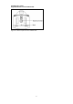
Asoka® User’s Guide PlugLink® 9850 IP Camera PL9850-CMS Chapter 6 Placement Options The PL9850-CMS can stand on a surface on its own or be mounted on a wall in several different ways. Depending on the positioning you want, you can attach the PL9850-CMS to its stand at two different points. Wall Option #1 1. Secure the base onto the wall by inserting three screws into the three available holes on the base unit. 2. Connect and secure the head connecter to the base unit. 3.
Asoka® User’s Guide PlugLink® 9850 IP Camera PL9850-CMS Chapter 7 Using the PlugLink 9850 IP Camera Utility The PlugLink 9850 IP Camera Utility allows your network administrator or security personnel to manage and monitor one or multiple PlugLink 9850 IP Cameras in your network through a single user interface. The utility can be used internally within your own network or externally from the Internet.
Asoka® User’s Guide PlugLink® 9850 IP Camera PL9850-CMS control and edit camera settings. . Using the Camera Function Bar: Figure 7-2: Camera Function Bar (A) Address: Click on the drop down menu. If your cameras have been set up properly, the Network Camera Utility should automatically detect the cameras and list the IP addresses of any cameras that are on the network. Highlight and select one of the IP addresses.
Asoka® User’s Guide PlugLink® 9850 IP Camera PL9850-CMS Figure 7-2a: Camera Address Sub-Menu This sub-menu allows you to configure the user name and password to access the camera. The default user name/password combination configured for the PlugLink 9850 IP Camera is: user/user. You may also change the Service Port number in the sub-menu. The Service Port is used by the camera to transmit the images. The default Service Port number configured in the PlugLink 9850 IP Camera is: 23721.
Asoka® User’s Guide PlugLink® 9850 IP Camera PL9850-CMS Recording. By default, the setting is set to 0 which disables the Motion Detection. You can input a number from 1 to 4 for this setting. The number indicates the level of sensitivity before the Network Camera Utility initiates the recording. Once you have set the motion detection settings, the Network Camera Utility software will take pictures of any motion that is detected during the specific time frame you set.
Asoka® User’s Guide PlugLink® 9850 IP Camera PL9850-CMS Figure 7-4: Capture Video Setup If you wish to input more time periods, simply enter the appropriate times under the Begin and End columns. The time periods are entered in 24-hour format (16:00 = 4 PM). Once you are finished, click on the Ok button. Note: You can record multiple screens concurrently. If you wish to record another screen, simply click on the screen you wish to record and repeat the process above.
Asoka® User’s Guide PlugLink® 9850 IP Camera PL9850-CMS the Play Video button and locate the file that the utility created. Controls to rewind, fast-forward, or stop the video will appear on the bottom left hand corner of the utility. Use them as needed to review the video that was created. Also, the recording time and date will be displayed in the upper hand corner of the video screen. Figure 7-6: Play Video Screen.
Asoka® User’s Guide PlugLink® 9850 IP Camera PL9850-CMS Chapter 8 Using the PlugLink 9850 IP Camera’s Web-based Utility You can use the PlugLink 9850 IP Camera’s web-based utility to access and alter its settings. This chapter will describe each webpage in the Utility and its features. The Utility can be accessed via the web browser of a computer connected to the camera. Please make sure your camera is configured and powered up. This section will describe some of the basic functions of the Web GUI.
Asoka® User’s Guide PlugLink® 9850 IP Camera PL9850-CMS Figure 8-2: Systems Details page Using the Operation Bar The Operation Bar is organized into four main sections: Motor Control; Video Control; Capture and Record; and System Functions.
Asoka® User’s Guide PlugLink® 9850 IP Camera PL9850-CMS Motor Control The Motor Control allows control of viewing angle of the camera. Figure 8-4: Motor Control (A) Automatically pan left and right. (B) Automatically tilt up and down. (C) Tilt the camera up. (D) Automatically pan up, down, left and right. (E) Tilt the camera right. (F) Tilt the camera down. (G) Tilt the camera left. Video Control Figure 8-5: Video Control (H) Autobright: Allows the camera to auto-adjust brightness and contrast.
Asoka® User’s Guide PlugLink® 9850 IP Camera PL9850-CMS (L) Hue: Adjust video hue from 0 to 31. (M) Rate: Adjust video frame rate from 0 to 15. (N) Valve: Adjust motion detection value from 0 to 4. (O) Frequency: Adjust video frequency from 0 to 1. [0=50Hz, 1=60Hz]. (P) View Size: Adjust video size from 0 to 3. [0=160x120, 1=176x144, 2=320x240, 3=640x480]. 5. Click on the Network button to access the Network settings for the IP Camera. Change any of the settings as needed to fit your network.
Asoka® User’s Guide PlugLink® 9850 IP Camera PL9850-CMS Figure 8-7: Powerline network encryption password screen Change the NEK as needed to match your power line network and then click the change button. You will be asked to reboot the camera. Click Reboot to save the changes. You may click on the Connect button in the Web GUI to view your camera at any time. Optionally, you may use the provided PlugLink 9850 IP Camera Utility to view your camera from any other PC in your network.
Asoka® User’s Guide PlugLink® 9850 IP Camera PL9850-CMS Chapter 9 Configuring the PlugLink 9850 for Remote Access Dynamic DNS Setup DSL/Cable ISPs generally provide dynamic IP addresses to their customers. This means an IP address that is assigned to a customer is temporary and will change after a certain period of time. This causes problems for users who wish to access their networks remotely.
Asoka® User’s Guide PlugLink® 9850 IP Camera PL9850-CMS the private IP Address of the PL9850 IP Camera. • Please consult your Cable/DSL router manual or manufacturer for more specific information on configuring port-forwarding or port-mapping. • If you are setting up multiple cameras, please repeat the above instructions above for each additional camera. Ensure each camera is using different IP addresses, Web Server Port number and Service Port numbers.
Asoka® User’s Guide PlugLink® 9850 IP Camera PL9850-CMS 2. In the Address field, enter your domain name. For example, mycamera.dyndns.org. 3. Click on the arrow that is below the Address field. This will open up a sub-menu with several more options. 4. Change the Service Port Number if needed. The default Service Port Number is 23721 which matches Camera #1 in our example above. 5. Click Add Camera Display to add your first camera. 6.
Asoka® User’s Guide PlugLink® 9850 IP Camera PL9850-CMS Chapter 10 Technical Support Information PLEASE REFER TO THE WARRANTY AND SUPPORT INFORMATION CARD THAT WAS SHIPPED WITH YOUR PRODUCT. By registering your product at www.asokausa.com/register, we can provide you with faster expert technical support and timely notices of product and software upgrades. Support Information Support hours are 6am-6pm pst Monday thru Friday, excluding U.S Holidays. Phone: 1-888-ASOKAUSA Email: support@asokausa.
Asoka® User’s Guide PlugLink® 9850 IP Camera PL9850-CMS Chapter 11 Glossary ACCESS - If you click on the Access button, you will be able to configure the access list for the PlugLink 9850 IP Camera. This will allow you to define which IPs can get into the camera and which cannot. AUTO CONFIG DNS – Click this box to have the DNS servers auto-assigned by your Router or other devices. Uncheck the box to manually enter your DNS servers. ALTERNATE DNS SERVER – Enter your secondary DNS server here.
Asoka® User’s Guide PlugLink® 9850 IP Camera PL9850-CMS PREFERED DNS SERVER – If the Auto-Config DNS box is unchecked, enter your primary DNS server here. SERVICE PORT – This is the port number the camera uses to transmit pictures. This can be changed as needed. SUBNET MASK – This is typically set to 255.255.255.0. You may adjust this as needed within your network. SYSTEM LOG - Click on the System Log button and you will be taken to the System Log screen.
Asoka® User’s Guide PlugLink® 9850 IP Camera PL9850-CMS Chapter 12 Technical Specifications Standards Compliance Processor HomePlug® I IEEE 802.3 Ethernet 32 Bits RISC Embedded cache, 8K-byte I-cacha,2K D-cache IEEE 802.3x Flow Control IEFT RFC783 Tftp IEFT RFC2131 DHCP Memory IEFT RFC1889 RTP/RTCP IEFT RFC2326 RTSP IEFT RFC2327 SDP Bandwidth IEFT RFC 2516 PPPOE DDNS Operating Frequency IEEE 802.
Asoka® User’s Guide PlugLink® 9850 IP Camera PL9850-CMS Chapter 13 FCC Statement This equipment has been tested and found to comply with the limits for a Class B digital device, pursuant to part 15 of FCC Rules. These limits are designed to provide reasonable protection against harmful interference in a residential installation.
Asoka® User’s Guide PlugLink® 9850 IP Camera PL9850-CMS Chapter 14 Warranty Information Asoka warrants that (a) the hardware components of the product will be free from defects in materials and workmanship under normal use for one (1) year from the date of purchase when used within the limits set forth in the Specifications section of the User Guide, and (b) the software components will perform substantially in accordance with Asoka’s published specifications for ninety (90) days from the date of purchase,
Asoka® User’s Guide PlugLink® 9850 IP Camera PL9850-CMS EXCLUDED. NEITHER ASOKA SHALL BE LIABLE, UNDER ANY CIRCUMSTANCES, TO ANY PERSON OR ENTITYFOR ANY SPECIAL, INCIDENTAL, INDIRECT OR CONSEQUENTIAL DAMAGES, INCLUDING WITHOUT LIMITATION, DAMAGES RESULTING FROM THE USE OR MALFUNCTION OF THE PRODUCTS, LOSS OF PROFITS OR REVENUES, BUSINESS INTERRUPTION, OR COSTS OF REPLACEMENT GOODS, EVEN IF ASOKA IS INFORMED IN ADVANCE OF THE POSSIBILITY OF SUCH DAMAGES.
Asoka® User’s Guide PlugLink® 9850 IP Camera PL9850-CMS Asoka USA Corporation 558 Pilgrim Drive Ste H Foster City CA 94404 Sales: (650) 286-1700; sales@asokausa.com Support: (888) ASOKAUSA; support@asokausa.com URL: www.asokausa.