
User Guide

1717
1717
17
ASRock 2Core1333-2.66G Motherboard
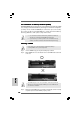
System Panel Header This header accommodates
(9-pin PANEL1) several system front panel
(see p.2 No. 13) functions.
Chassis Speaker Header Please connect the chassis
(4-pin SPEAKER 1) speaker to this header.
(see p.2 No. 15)
Chassis Fan Connector Please connect a chassis fan
(3-pin CHA_FAN1) cable to this connector and
(see p.2 No. 16) match the black wire to the
ground pin.
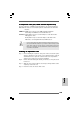
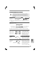
CPU Fan Connector Please connect a CPU fan cable
(4-pin CPU_FAN1) to this connector and match
(see p.2 No. 3) the black wire to the ground pin.
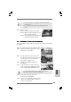
F. Enter Windows system. Click the icon on the lower right hand
taskbar to enter Realtek HD Audio Manager. Click “Audio I/O”,
select “Connector Settings” , choose “Disable front
panel jack detection”, and save the change by clicking “OK”.
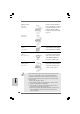
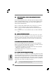
Though this motherboard provides 4-Pin CPU fan (Quiet Fan) support, the 3-Pin
CPU fan still can work successfully even without the fan speed control function.
If you plan to connect the 3-Pin CPU fan to the CPU fan connector on this
motherboard, please connect it to Pin 1-3.
3-Pin Fan Installation
Pin 1-3 Connected
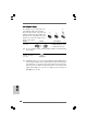
ATX Power Connector Please connect an ATX power
(20-pin ATXPWR1) supply to this connector.
(see p.2 No. 26)
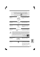
ATX 12V Connector Please note that it is necessary
(4-pin ATX12V1) to connect a power supply with
(see p.2 No. 2) ATX 12V plug to this connector
so that it can provides sufficient
power. Failing to do so will cause
the failure to power up.
1 2 3 4
EnglishEnglish
EnglishEnglish
English