
User manual


2424
2424
24
MID I_OUT
JAB2
JBY
JBB2
MID I_IN
+5V
JAY
GND
GND
1
JAX
JAB1
+5V
JBX
JBB1
+5V
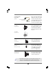
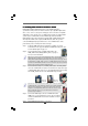
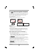
Game Connector Connect a Game cable to this
(15-pin GAME1) connector if the Game port
(see p.11, No. 22) bracket is installed.
ATX Power Connector Please connect an ATX power
(20-pin ATXPWR1) supply to this connector.
(see p.11, No. 29)
ATX 12V Connector Please note that it is necessary
(4-pin ATX12V1) to connect a power supply with
(see p.11, No. 2) ATX 12V plug to this connector
so that it can provides sufficient
power. Failing to do so will cause
the failure to power up.
1
GND
+5 V
SPDIFOUT
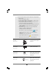
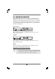
HDMI_SPDIF Header HDMI_SPDIF header, providing
(3-pin HDMI_SPDIF1) SPDIF audio output to HDMI VGA
(see p.11 No. 23) card, allows the system to
connect HDMI Digital TV/
projector/LCD devices. Please
connect the HDMI_SPDIF
connector of HDMI VGA card to
this header.
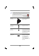
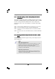
Though this motherboard provides 4-Pin CPU fan (Quiet Fan) support, the 3-Pin
CPU fan still can work successfully even without the fan speed control function.
If you plan to connect the 3-Pin CPU fan to the CPU fan connector on this
motherboard, please connect it to Pin 1-3.
3-Pin Fan Installation
Pin 1-3 Connected