Copyright Notice: No part of this installation guide may be reproduced, transcribed, transmitted, or translated in any language, in any form or by any means, except duplication of documentation by the purchaser for backup purpose, without written consent of ASRock Inc.
Motherboard LLayout ayout English 1 2 3 4 5 6 7 8 9 10 11 12 13 14 15 PS2_USB_PWR1 Jumper 16 ATX Power Connector (ATXPWR1) 17 ATX 12V Connector (ATX12V1) 18 775-Pin CPU Socket 19 CPU Fan Connector (CPU_FAN1) North Bridge Controller 20 2 x 240-pin DDR2 DIMM Slots 21 (DDRII_1 and DDRII_2; Yellow) 22 IDE1 Connector (IDE1, Blue) 23 Serial Port Connector (COM1) 24 Clear CMOS Jumper (CLRCMOS1) 25 System Panel Header (PANEL1) 26 Fourth SATAII Connector (SATAII_4 (PORT1.
ASRock 6CH_DVI I/O 1 2 3 4 5 *6 PS/2 Mouse Port (Green) Parallel Port RJ-45 Port Line In (Light Blue) Front Speaker (Lime) Microphone (Pink) 7 8 9 10 11 USB 2.0 Ports (USB23) USB 2.0 Ports (USB01) VGA/D-Sub Port VGA/DVI-D Port PS/2 Keyboard Port (Purple) * To enable Multi-Streaming function, you need to connect a front panel audio cable to the front panel audio header. Please refer to below steps for the software setting of Multi-Streaming.
1. Introduction Thank you for purchasing ASRock 4CoreN73PV-HD720p motherboard, a reliable motherboard produced under ASRock’s consistently stringent quality control. It delivers excellent performance with robust design conforming to ASRock’s commitment to quality and endurance. This Quick Installation Guide contains introduction of the motherboard and step-bystep installation guide. More detailed information of the motherboard can be found in the user manual presented in the Support CD.
Specifications Platform CPU Chipset Memory Hybrid Booster Expansion Slot Graphics Audio LAN Rear Panel I/O - Micro ATX Form Factor: 9.6-in x 8.0-in, 24.4 cm x 20.
Connector BIOS Feature Support CD Hardware Monitor OS Certifications - 1 x RJ-45 Port - HD Audio Jack: Line in/Front Speaker/Microphone - 4 x Serial ATAII 3.
CAUTION! About the setting of “Hyper Threading Technology”, please check page 40 of “User Manual“ in the support CD. 2. This motherboard supports Untied Overclocking Technology. Please read “Untied Overclocking Technology” on page 30 for details. 3. Due to the operating system limitation, the actual memory size may be less than 4GB for the reservation for system usage under Windows® XP and Windows® VistaTM. For Windows® XP 64-bit and Windows® VistaTM 64-bit with 64-bit CPU, there is no such limitation. 4.
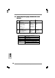
1.3 Minimum Hardware R equirement TTable able for Requirement ® TM Windows Vista Premium 2007 and Basic Logo For system integrators and users who purchase this motherboard and plan to submit Windows® VistaTM Premium 2007 and Basic logo, please follow below table for minimum hardware requirements. CPU Memory VGA Celeron D 326 1GB system memory (Premium) 512MB Single Channel (Basic) DX9.
Minimum Hardware Requirement for 720p Blu-ray VD Playback Suppor -DVD Supportt (BD) / HD -D 720p Blu-ray (BD) / HD-DVD playback support on this motherboard requires the proper hardware configuration. Please refer to below table for the minimum hardware requirement. CPU VGA Memory Suggested OS Wolfdale E8500 Onboard VGA with DVI-D port DDR2 800, 1GB x 2 Windows® VistaTM or Windows® VistaTM 64 * If you need to use CyberLink PowerDVD Ultra version 7.2 or 7.
1.
2. Installation Pre-installation Precautions Take note of the following precautions before you install motherboard components or change any motherboard settings. 1. Unplug the power cord from the wall socket before touching any component. Failure to do so may cause severe damage to the motherboard, peripherals, and/or components. 2. To avoid damaging the motherboard components due to static electricity, NEVER place your motherboard directly on the carpet or the like.
Step 1. Open the socket: Step 1-1. Disengaging the lever by depressing down and out on the hook to clear retention tab. Step 1-2. Rotate the load lever to fully open position at approximately 135 degrees. Step 1-3. Rotate the load plate to fully open position at approximately 100 degrees. black line black line Step 2. Insert the 775-LAND CPU: Step 2-1. Hold the CPU by the edges where are marked with black lines. Step 2-2. Orient the CPU with IHS (Integrated Heat Sink) up.
1. It is recommended to use the cap tab to handle and avoid kicking off the PnP cap. 2. This cap must be placed if returning the motherboard for after service. Step 4. Close the socket: Step 4-1. Rotate the load plate onto the IHS. Step 4-2. While pressing down lightly on load plate, engage the load lever. Step 4-3. Secure load lever with load plate tab under retention tab of load lever. 2.
2.3 Installation of Memor y Modules (DIMM) This motherboard provides two 240-pin DDR2 (Double Data Rate 2) DIMM slots. Please make sure to disconnect power supply before adding or removing DIMMs or the system components. Step 1. Step 2. Unlock a DIMM slot by pressing the retaining clips outward. Align a DIMM on the slot such that the notch on the DIMM matches the break on the slot. The DIMM only fits in one correct orientation.
2.4 Expansion Slots (PCI and PCI Express Slots) There are 2 PCI slots and 2 PCI Express slots on this motherboard. PCI slots: PCI slots are used to install expansion cards that have the 32-bit PCI interface. PCIE slots: PCIE1 (PCIE x1 slot) is used for PCI Express cards with x1 lane width cards, such as Gigabit LAN card, SATA2 card, etc. PCIE2 (PCIE x16 slot) is used for PCI Express cards with x16 lane width graphics cards. Installing an expansion card Step 2. Step 3. Step 4.
2.5 Dual Monitor and Surround Display Features Dual Monitor Feature This motherboard supports dual monitor feature. With the internal dual VGA output support (DVI-D and D-Sub), you can easily enjoy the benefits of dual monitor feature without installing any add-on VGA card to this motherboard. This motherboard also provides independent display controllers for DVI-D and D-Sub to support dual VGA output so that DVI-D and D-sub can drive same or different display contents.
English Surround Display Feature This motherboard supports surround display upgrade. With the internal dual VGA output support (DVI-D and D-Sub) and the external add-on PCI Express VGA card, you can easily enjoy the benefits of surround display feature. Please refer to the following steps to set up a surround display environment: 1. Install the NVIDIA® PCI Express VGA card to PCIE2 slot. Please refer to page 15 for proper expansion card installation procedures for details. 2.
A. Click the number ”2” icon. B. Click the items “This is my main monitor” and “Extend the desktop onto this monitor”. C. Click “OK” to save your change. D. Repeat steps A through C for the display icon identified by the number three and four. 6. Use Surround Display. Click and drag the display icons to positions representing the physical setup of your monitors that you would like to use. The placement of display icons determines how you move items from one monitor to another.
2.6 Jumpers Setup The illustration shows how jumpers are setup. When the jumper cap is placed on pins, the jumper is “Short”. If no jumper cap is placed on pins, the jumper is “Open”. The illustration shows a 3-pin jumper whose pin1 and pin2 are “Short” when jumper cap is placed on these 2 pins. Jumper Setting PS2_USB_PWR1 Short Open Description Short pin2, pin3 to enable (see p.2 No. 1) +5VSB (standby) for PS/2 or USB wake up events.
2.7 Onboard Headers and Connectors Onboard headers and connectors are NOT jumpers. Do NOT place jumper caps over these headers and connectors. Placing jumper caps over the headers and connectors will cause permanent damage of the motherboard! FDD connector (33-pin FLOPPY1) (see p.2 No. 18) the red-striped side to Pin1 Note: Make sure the red-striped side of the cable is plugged into Pin1 side of the connector. Primary IDE connector (Blue) (39-pin IDE1, see p.2 No.
Serial ATA (SATA) Power Cable Please connect the black end of SATA power cable to the power (Optional) connector on each drive. Then connect the white end of SATA power cable to the power connector of the power supply. connect to the SATA HDD power connector connect to the power supply USB 2.0 Headers Besides four default USB 2.0 ports on the I/O panel, there are two USB 2.0 headers on this motherboard. Each USB 2.0 header can support two USB 2.0 ports. (9-pin US6_7) (see p.2 No.
Front Panel Audio Header (9-pin HD_AUDIO1) (see p.2 No. 21) This is an interface for front panel audio cable that allows convenient connection and control of audio devices. 1. High Definition Audio supports Jack Sensing, but the panel wire on the chassis must support HDA to function correctly. Please follow the instruction in our manual and chassis manual to install your system. 2. If you use AC’97 audio panel, please install it to the front panel audio header as below: A. Connect Mic_IN (MIC) to MIC2_L.
Chassis Fan Connector Please connect a chassis fan cable to this connector and match the black wire to the ground pin. (3-pin CHA_FAN1) (see p.2 No. 16) CPU Fan Connector Please connect a CPU fan cable to this connector and match the black wire to the ground pin. 4321 (4-pin CPU_FAN1) (see p.2 No. 5) Though this motherboard provides 4-Pin CPU fan (Quiet Fan) support, the 3-Pin CPU fan still can work successfully even without the fan speed control function.
2.8 SA SATTAII Hard Disk Setup Guide Before installing SATAII hard disk to your computer, please carefully read below SATAII hard disk setup guide. Some default setting of SATAII hard disks may not be at SATAII mode, which operate with the best performance. In order to enable SATAII function, please follow the below instruction with different vendors to correctly adjust your SATAII hard disk to SATAII mode in advance; otherwise, your SATAII hard disk may fail to run at SATAII mode.
2.9 Serial A ATTA (SA (SATTA) / Serial A ATTAII (SA (SATTAII) Hard Disks Installation This motherboard adopts NVIDIA® GeForce 7100 / nForce 630i chipset that supports Serial ATA (SATA) / Serial ATAII (SATAII) hard disks and RAID functions. You may install SATA / SATAII hard disks on this motherboard for internal storage devices. This section will guide you to install the SATA / SATAII hard disks. STEP 1: Install the SATA / SATAII hard disks into the drive bays of your chassis.
2 . 1 1 Driver Installation Guide To install the drivers to your system, please insert the support CD to your optical drive first. Then, the drivers compatible to your system can be auto-detected and listed on the support CD driver page. Please follow the order from up to bottom side to install those required drivers. Therefore, the drivers you install can work properly. 2 .
Please insert a floppy diskette into the floppy drive. Select your required item on the list according to the mode you choose and the OS you install. Then press any key. E. The system will start to format the floppy diskette and copy SATA / SATAII drivers into the floppy diskette. STEP 3: Install Windows® XP / XP 64-bit OS on your system. After making a SATA / SATAII driver diskette, you can start to install Windows® XP / XP 64-bit on your system.
(There are two ASRock Support CD in the motherboard gift box pack, please choose the one for Windows® VistaTM / VistaTM 64-bit.) .. \ I386 \ AHCI_Vista (For Windows® VistaTM OS) .. \ AMD64\ AHCI_Vista64 (For Windows® VistaTM 64-bit OS) After that, please insert Windows® VistaTM / Windows® VistaTM 64-bit optical disk into the optical drive again to continue the installation. Using SATA / SATAII HDDs without NCQ and Hot Plug functions STEP 1: Set Up BIOS. A.
STEP 4: Install Windows® XP / XP 64-bit OS on your system. After step1, 2, 3, you can start to install Windows® XP / Windows® XP 64-bit OS on your system. At the beginning of Windows® setup, press F6 to install a third-party RAID driver. When prompted, insert the SATA / SATAII driver diskette containing the NVIDIA® RAID driver. After reading the floppy disk, the drivers will be presented. Select the drivers to install. The drivers are as below: A. NVIDIA RAID Driver (required) B.
After that, please insert Windows® VistaTM / Windows® VistaTM 64-bit optical disk into the optical drive again to continue the installation. NOTE. If you install Windows® VistaTM / Windows® VistaTM 64-bit on IDE HDDs and want to manage (create, convert, delete, or rebuild) RAID functions on SATA / SATAII HDDs, you still need to set up “SATA Operation Mode” to [RAID] in BIOS first. Then, please set the RAID configuration by using the Windows RAID installation guide in the following path in the Support CD: ..
3. BIOS Information The Flash Memory on the motherboard stores BIOS Setup Utility. When you start up the computer, please press during the Power-On-Self-Test (POST) to enter BIOS Setup utility; otherwise, POST continues with its test routines. If you wish to enter BIOS Setup after POST, please restart the system by pressing + + , or pressing the reset button on the system chassis. The BIOS Setup program is designed to be user-friendly.
ASRock 4CoreN73PV-HD720p Motherboard
® ® ® ® ® ® 33 ASRock 4CoreN73PV-HD720p Motherboard
® 34 ASRock 4CoreN73PV-HD720p Motherboard
“ ” ® ® ® ® ® “ 35 ASRock 4CoreN73PV-HD720p Motherboard
® ® ® ® ® ® ® 36 ASRock 4CoreN73PV-HD720p Motherboard
ASRock 4CoreN73PV-HD720p Motherboard
Pin1 Pin1 38 ASRock 4CoreN73PV-HD720p Motherboard
ASRock 4CoreN73PV-HD720p Motherboard
ASRock 4CoreN73PV-HD720p Motherboard
ASRock 4CoreN73PV-HD720p Motherboard
ASRock 4CoreN73PV-HD720p Motherboard
® “ ” “ ” ® “ “ ” ” “ ” “ ” “ ” “ “ ” ” “ “ ” ” “ ” 43 ASRock 4CoreN73PV-HD720p Motherboard
® ” “ ” “ ” “ “ ” ” “ ” ® 44 ASRock 4CoreN73PV-HD720p Motherboard
“ ” “ “ ” ” “ ” 45 ASRock 4CoreN73PV-HD720p Motherboard
ASRock 4CoreN73PV-HD720p Motherboard SATAII_4 (PORT1.3) SATAII_3 (PORT1.2) SATAII_2 (PORT1.1) SATAII_1 (PORT1.
CD1 47 ASRock 4CoreN73PV-HD720p Motherboard
® ® ® 48 ASRock 4CoreN73PV-HD720p Motherboard
4 3 2 1 12 24 1 13 12 24 1 13 49 ASRock 4CoreN73PV-HD720p Motherboard
ASRock 4CoreN73PV-HD720p Motherboard
® ® “ “ ” ” 51 ASRock 4CoreN73PV-HD720p Motherboard
® ® ® ® ® ® ® ® 52 ASRock 4CoreN73PV-HD720p Motherboard
® ® ® ® A. NVIDIA nForce Storage Controller (required) Windows XP B.
\ \ ® \ ® \ ® ® ® ® ® ® \ “ ” 54 ASRock 4CoreN73PV-HD720p Motherboard
“ “ ” ” \ \ 55 ASRock 4CoreN73PV-HD720p Motherboard
ASRock 4CoreN73PV-HD720p Motherboard
® ® ® ® ® ® 57 ASRock 4CoreN73PV-HD720p Motherboard
® ® 58 ASRock 4CoreN73PV-HD720p Motherboard
® ® ® ® ® ® 59 ASRock 4CoreN73PV-HD720p Motherboard
® ® ® ® ® ® ® 60 ASRock 4CoreN73PV-HD720p Motherboard
ASRock 4CoreN73PV-HD720p Motherboard
ASRock 4CoreN73PV-HD720p Motherboard
ASRock 4CoreN73PV-HD720p Motherboard
ASRock 4CoreN73PV-HD720p Motherboard
ASRock 4CoreN73PV-HD720p Motherboard
ASRock 4CoreN73PV-HD720p Motherboard
® ® ® 67 ASRock 4CoreN73PV-HD720p Motherboard
® 68 ASRock 4CoreN73PV-HD720p Motherboard
ASRock 4CoreN73PV-HD720p Motherboard
ASRock 4CoreN73PV-HD720p Motherboard SATAII_4 (PORT1.3) SATAII_3 (PORT1.2) SATAII_2 (PORT1.1) SATAII_1 (PORT1.
CD1 71 ASRock 4CoreN73PV-HD720p Motherboard
® ® 4321 72 ASRock 4CoreN73PV-HD720p Motherboard
12 24 1 13 12 24 1 13 73 ASRock 4CoreN73PV-HD720p Motherboard
ASRock 4CoreN73PV-HD720p Motherboard
® ® 75 ASRock 4CoreN73PV-HD720p Motherboard
® ® ® ® ® ® ® ® 76 ASRock 4CoreN73PV-HD720p Motherboard ®
® ® ® ® A. NVIDIA nForce Storage Controller (required) Windows XP B.
® ® ® ® ® ® ® ® ® ® ® 78 ASRock 4CoreN73PV-HD720p Motherboard
® ® 79 ASRock 4CoreN73PV-HD720p Motherboard
X O O O O O X O O O O O O: X: 80 ASRock 4CoreN73PV-HD720p Motherboard
NOTE. If you install the VGA driver (version 163.91) on your system, but the window is not in full screen mode, please follow below steps to adjust the window. 1. Right-click the desktop and select NVIDIA Control Panel. 2. Click Display and click Change Flat Panel Scaling. 3. In the option When using a resolution lower than my display’s native resolution, please select Use my display’s built-in scaling.