
Computer Hardware User Manual

2121
2121
21
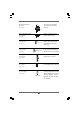
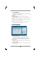
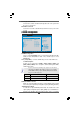
System Panel Header This header accommodates
(9-pin PANEL1) several system front panel
(see p.9 No. 18) functions.
Chassis Speaker Header Please connect the chassis
(4-pin SPEAKER 1) speaker to this header.
(see p.9 No. 16)
Chassis Fan Connector Please connect a chassis fan
(3-pin CHA_FAN1) cable to this connector and
(see p.9 No. 17) match the black wire to the
ground pin.
CPU Fan Connector Please connect a CPU fan cable
(4-pin CPU_FAN1) to this connector and match
(see p.9 No. 5) the black wire to the ground pin.
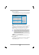
ATX Power Connector Please connect an ATX power
(20-pin ATXPWR1) supply to this connector.
(see p.9 No. 36)
ATX 12V Connector Please connect an ATX 12V
(4-pin ATX12V1) power supply to this connector.
(see p.9 No. 2)
SLI Power Connector It is not necessary to use this
(4-pin SLI_POWER1) connector, but please connect it
(see p.9 No. 34) with a hard disk power connecor
when two graphics cards are
plugged to this motherboard at
the same time.
G ND
+12 V
CHA_FAN_SPEED
+5V
DUMMY
DUMMY
SPEAKER
1
GND
PWRBTN#
PLED-
PLED+
DUMMY
RESET#
GND
HDLED+
HDLED-
1
GND
+12V
C PU_FAN_SPEED
FAN_SPEED_CONTROL
SLI POWER_1