SuperDVR & WS 401 Series Cards SUPERDVR & WS 401 USB/SERIES CARDS 1
SuperDVR & WS 401 Series Cards 2 CONTENTS INTRODUCTION......................................................................................... 7 SUMMARIZATION ..................................................................................... 7 SYSTEM REQUIREMENTS..................................................................... 10 WS 401 SERIES CARDS SYSTEM REQUIREMENTS......................... 10 TD 3316 SYSTEM REQUIREMENTS .....................................................
SuperDVR & WS 401 Series Cards 3 DISPLAY CONTROL PANEL.......................................................................... 33 LOGIN ........................................................................................................ 35 RECORD ..................................................................................................... 36 Record Modes ....................................................................................... 36 Record Setup ...................................
SuperDVR & WS 401 Series Cards 4 USERS CONFIGURATION....................................................................... 64 CHANGE USER RIGHTS ............................................................................... 65 Add User ............................................................................................... 66 Delete User ........................................................................................... 66 PTZ CONTROL ......................................................
SuperDVR & WS 401 Series Cards 5 Appendix 2.1.2 Why cannot run SuperDVR at the windows 2003 operate system?................................................................................................ 118 Appendix 2.1.3 ‘Unspecified error’ in the End of Installation ............ 118 Appendix 2.1.4 Can’t find TD series Devices in Device Manager ...... 119 APPENDIX 2.2 HOW TO USE SUPERDVR.................................................. 119 Appendix 2.2.1 Meanings of the indicator lights ...............
SuperDVR & WS 401 Series Cards 6 area when play back?.......................................................................... 125 Appendix 2.4.7 Why do I see some old record sections that can’t be covered when play back? .................................................................... 126 APPENDIX 3 QUICK START FOR USING .......................................... 126 APPENDIX 4 FUNCTION TREE ...........................................................
SuperDVR & WS 401 Series Cards 7 Introduction Summarization Thank you for choosing our digital video capture cards. 1 Channel, 4 Channel, 8 Channel and 16 Channel cards adopt MPEG4 compression format, and enable maximum 16 channels real-time or none real-time surveillance. Our cards are mature and cost-effective products that should be your ideal choices. They enable synchronous audio and video compression and transmission, with their powerful compression rate and network transmission function.
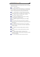
SuperDVR & WS 401 Series Cards 8 (2) Motion detection mode Motion detection areas are adjustable and maximum 16 areas for each channel. Users can also set motion detection sensitivity for each channel. The system begins to record only when motion of the detected object happens, and it will stop recording after a certain period, this function is adjustable by users. (3) Sensor alarm record mode With extra alarm board, the system enables alarm input and output.
SuperDVR & WS 401 Series Cards 9 Support different multi-channel display modes, full screen display and auto dwell display. (8) Watch dog function The 16 Channels card has watchdog function. In case SuperDVR driver or windows system is frozen, the watchdog will restart the computer and login SuperDVR system again automatically. (9) One PC support 1 to 4 cards of the same model, the maximum frame rate can be 200 fps and 16 channels at most.
SuperDVR & WS 401 Series Cards 10 technology (19) Remote Surveillance and PTZ control through LAN, Intranet, and Internet. (20) Support alarm pre-record. (21) Support buzzer, email alarm out. (22) Can greatly decrease fragmented files while using NTFS partition. (23) User-friendly graphical user interface.
SuperDVR & WS 401 Series Cards 11 GA-8IPE1000-G (Intel 865PE) ASUS: P4S8X (Sis 648) TUSL2-C (Intel 815EP) P4P800 (Intel 865PE) MSI: MS-6566E (Intel 845E) Intel845DDA+ (Intel 845E) TD 3316 system requirements Card WS 401 PC Module CPU Intel P4 2.8G minimum Motherboard Intel 865/915 HDD 160G minimum RAM 512M minimum VGA NVIDIA GeForce MX440/FX5200 ATI RADEON 7500/ X300/ X250/ X5518 OS Windows 2000(SP4 above)/ Windows XP(SP1above) DirectX 9.0 Table 1.
SuperDVR & WS 401 Series Cards 12 ASUS-P4GPL-X 915(Intel 915) ASROCK 775I915PL-SATA2 915(Intel 915) WS 401 USB cards system requirements Card WS 401 PC Module CPU Intel P4 Celeron processor,minimum 1700MHz Motherboard Intel 845/865/915 series HDD 80G minimum RAM 256M minimum VGA GeForce2,GeForce4,FX5200,ATI Rage128 OS Windows 2000(SP4 above)/2003(SP1 above)/XP(SP2 above) DirectX 9.0 USB 2.0 Table 1.
SuperDVR & WS 401 Series Cards 13 Notice, motherboards listed below which has passed the test can work well with TD 4104: ASROCK 775I915PL-SATA2 Asus P4p800SE ASUS P5VDC-X GA G8i845GVW-RZ GA-k8vT890 MSI 865PE IWILL i845G Foxconn 865GV Special Notice: If recorded disk partition’s format is FAT32 and the system has run for a long time, the system will create a lot of data fragments that may results in system runs slowly. It’s recommended to make disk defragmenter every 10 to 30 days.
SuperDVR & WS 401 Series Cards 14 Data format: MPEG4 Hardware installation Video Capture Card Hardware WS 401 Card Hardware Figure 2.
SuperDVR & WS 401 Series Cards 15 Pin Port Define Interpret 10PIN ALARM_IN4 Alarm Input 4 Table 2.1 WS 401 card pins TD WS 401 Card Hardware Figure 2.
SuperDVR & WS 401 Series Cards 16 Figure 2.3 pin definitions of TD 3008 Video Capture Card WS 401 Card Hardware Figure 2.4 WS 401Video Capture Card circuit link for Watchdog function Figure 2.
SuperDVR & WS 401 Series Cards 17 Pin Port Define Interpret Pin Port Define Interpret Pin3 Alarm_in3 Alarm Input 3 Pin23 Alarm_out7 Alarm Output 7 Pin4 Alarm_in4 Alarm Input 4 Pin24 Alarm_out8 Alarm Output 8 Pin5 Alarm_in5 Alarm Input 5 Pin25 Alarm_out9 Alarm Output 9 Pin6 Alarm_in6 Alarm Input 6 Pin26 Alarm_out10 Alarm Output 10 Pin7 Alarm_in7 Alarm Input 7 Pin27 Alarm_out11 Alarm Output 11 Pin8 Alarm_in8 Alarm Input 8 Pin28 Alarm_out12 Alarm Output 12 Pin9 Alar
SuperDVR & WS 401 Series Cards 18 WS 401 Card Hardware Figure 2.6 TD 3116 Video Capture Card Figure 2.
SuperDVR & WS 401 Series Cards Figure 2.8 Pins definitions of Video Capture Card TD 3216 Card Hardware Figure 2.
SuperDVR & WS 401 Series Cards Figure 2.10 Pins definitions of Video Capture Card TD 3316 Card Hardware Figure 2.
SuperDVR & WS 401 Series Cards 21 P2 DFD202-F-26-R-T 10 19 11 20 12 21 13 22 14 23 15 24 16 25 17 26 18 1 2 3 4 5 6 7 8 27 28 9 Figure 2.12 Audio Connector PIN1 AUDIO2 PIN11 AUDIO3 PIN2 AUDIO4 PIN12 AUDIO5 PIN3 AUDIO6 PIN13 AUDIO7 PIN4 AUDIO8 PIN14 AUDIO9 PIN5 AUDIO10 PIN15 AUDIO11 PIN6 AUDIO12 PIN16 AUDIO13 PIN7 AUDIO14 PIN17 PIN8 AUDIO15 PIN9 AUDIO16 / PIN10 AUDIO1 PIN26 GND Table 2.
SuperDVR & WS 401 Series Cards J1 GiL-G-8P-S3T2-E 1 2 3 4 5 6 7 8 J2 GiL-G-8P-S3T2-E 1 2 3 4 5 6 7 8 J3 GiL-G-8P-S3T2-E 1 2 3 4 5 6 7 8 J4 GiL-G-8P-S3T2-E 1 2 3 4 5 6 7 8 22 PIN1 VIN-1 PIN2 GND PIN3 VIN-2 PIN4 GND PIN5 VIN-3 PIN6 GND PIN7 VIN-4 PIN8 GND PIN1 VIN-9 PIN1 PIN2 VIN-5 GND PIN2 PIN3 GND VIN-10 PIN3 PIN4 VIN-6 GND PIN4 PIN5 GND VIN-11 PIN5 PIN6 VIN-7 GND PIN6 PIN7 GND VIN-12 PIN7 PIN8 VIN-8 GND PIN8 GND
SuperDVR & WS 401 Series Cards 23 Figure 2.13 Video PINs definition TD 3101 USB Card Hardware Audio input(white) Video input (yellow) USB Connection Figure 2.
SuperDVR & WS 401 Series Cards 24 WS 401USB Card Hardware Audio input (white) Video input (yellow) USB Connection Figure 2.15 WS 401 USB Video Capture Card Notice: Make sure that your PC USB interface is 2.0; WS 401 card can only support USB 2.0. Please accord to the following steps to safely remove the USB card: Right clicks on the Taskbar Stop device pull out the USB card. Using WS 401 card with other USB device simultaneously may because PC cannot identify USB card.
SuperDVR & WS 401 Series Cards 25 WS 401 Card Hardware PIN1 AUDIO-1 PIN2 GND PIN3 AUDIO-2 PIN4 GND PIN5 AUDIO-3 PIN6 GND PIN7 AUDIO-4 PIN8 GND Figure 2.16 WS 401 Video Capture Card J5 GiL-G-8P-S3T2-E 1 2 3 4 5 6 7 Table 2.
SuperDVR & WS 401 Series Cards 26 PIN1 VIDEO-1 PIN9 GND PIN2 GND PIN10 AUDIO-1 PIN3 VIDEO-2 PIN11 AUDIO-2 PIN4 GND PIN12 AUDIO-3 PIN5 VIDEO-3 PIN13 AUDIO-4 PIN6 GND PIN14 NULL PIN7 VIDEO-4 PIN15 GND PIN8 GND Figure 2.18 Video Capture Card Table 2.
SuperDVR & WS 401 Series Cards Alarm Board Hardware Figure 2.18 Alarm Board Figure 2.
SuperDVR & WS 401 Series Cards 28 Connect J2 to PC serial port and you may use alarm board by SuperDVR system. Connect Audio Signal For WS 401, connect the audio input device to the microphone connector on the motherboard. Note: Before installing the Video Capture Card hardware in PCI port of the motherboard, make sure you’ve installed Microsoft DirectX 9.0. Then turn on the computer, the system will remind you to “Found new hardware”. Notice: Just click “cancel” and ignore the pop-up message.
SuperDVR & WS 401 Series Cards Figure 2.30 WS series video capture card installation interface Figure 2.
SuperDVR & WS 401 Series Cards Select ‘Next’, Figure 2.32 Select video formats Select ‘Next’, Figure 2.
SuperDVR & WS 401 Series Cards Figure 2.34 Select installationpass Select the suitable option, and click ‘Next’. Figure 2.
SuperDVR & WS 401 Series Cards 32 Click ‘Next’, Figure 2.36 Driver and application installation finished Click ‘Finish’ Now, after all the processes are finished, restart the computer and launch the surveillance program. It will create a shortcut on the desktop. Figure 2.37 Shortcut of SuperDVR Notice: In case users cannot run the SuperDVR program, users restart the computer.
SuperDVR & WS 401 Series Cards 33 Main display Interface Run SuperDVR program and the main display interface appear as below: Figure 3.1 SuperDVR Main Display Interface Display Control Panel Display Control Panel Figure 3.
SuperDVR & WS 401 Series Cards 34 free space indicator, ‘Auto Dwell’ button, 1, 4, 6, 8, 9, 13, 16channels display buttons. Every button has its built-in indicator light. When switch on and off the buttons, the relative indicator lights turn on and off to indicate the working status. Notice: Users can judge which buttons are working by the color of the buttons. Free Display Modes 1C 4CH 6CH 8CH 9CH 13CH 16C Figure 3.
SuperDVR & WS 401 Series Cards 35 click , system will display the next page according to the display mode. Auto Dwell display Mode In case users want to see all the channels in sequence, then click and enter Auto Dwell display mode. Quick Switch In case the present display mode is 4 ch, 9 ch or 16 ch, by clicking any image or the present display mode is 6 ch, 8 ch or 13 ch, by clicking the bigger image, the display will quickly switch to corresponding single channel display mode.
SuperDVR & WS 401 Series Cards 36 Time & Logi Search Configurat PTZ Control Exit Display Mode Alarm out Camera Figure 3.4 Main Interface Record Record Modes According to different record triggering methods, TD series video capture cards offer users with 4 kinds of record modes: Schedule record mode (timer) Manual record mode Motion Detection record mode Sensor Alarm record mode Motion Detection record mode and Sensor Alarm record mode are together called as Alarm Record.
SuperDVR & WS 401 Series Cards 37 separately and the record file also saved separately. The parameters, i.e. camera ID, record date/time and record mode are all saved together with the record file. Record Setup Figure 3.5 Record ConfigurationPanel In the ‘Record Panel’ of the Basic Configuration page, users can set all kinds of necessary parameters for recording. [Time stamp]: By selecting the options, the record date / time message appears in the record file images.
SuperDVR & WS 401 Series Cards 38 relative channels’ record mode as motion detection [Motion Record Frame Rate]: Select record frame rate for Motion Detection record mode [Sensor Record Frame Rate]: If sensors are utilized to trigger recording, users can select record frame rate here. [Camera Security]: The users are divided into three standards: Normal user, Power user and Administrator. By selecting the options, only administrators can see the corresponding channels.
SuperDVR & WS 401 Series Cards (4) Motion Detection Record State (5) Sensor Alarm Record State (6) Video Loss State When the indicator light color turns into 39 in row two, it means there is alarm output. Manual Record Mode Manual Record mode is the most commonly used record mode. In case there is any special event happens, users can select this record mode and record timely.
SuperDVR & WS 401 Series Cards 40 movement, the system won’t record and that’s helpful for saving system resource, and convenient for searching for event record file. The indicator light color in the record status panel is yellow . Note: Users may need to setup in three places so as to enable motion detection record.
SuperDVR & WS 401 Series Cards 41 Users can set recording storage sequence for HDD partitions. The recording storage will automatically jump to the next partition when it’s full. If all the partitions are full and recycling record mode has been enabled, the new data will overwrite the former recorded data automatically. Users can also set HDD minimum storage alarm.
SuperDVR & WS 401 Series Cards Figure 4.1 Basic Configuration The definitions of the buttons in Figure 4.
SuperDVR & WS 401 Series Cards 43 Basic Configuration Click and enter the basic configuration page where users can setup the system or just use the defaults. Figure 4.2 Captions and General Configuration [Dwell Interval.]: If users enable Auto Dwell function in the main interface page, users can set the dwell time of a page here. [Caption]: There are four options, None, ID, Name and ID/Name for users to Select for all the channels. ‘None’ means no title; ‘ID’ means camera numbers, i.e.
SuperDVR & WS 401 Series Cards 44 video may have interlace lines if the users select 640x480, users may choose for solve this problem, but it will occupy much more CPU loading. [Call Monitor] Only TD3016, TD3216 and TD3316 have call monitor function at present. Users can connect another monitor to the card and select the display modes here. The following is about record data storage. Please check Figure 4.3. Figure 4.
SuperDVR & WS 401 Series Cards 45 Then when restarting the computer system, it will access to the system with the user name and password input in the boxes. Figure 4.4 Computer System Reboot setups As the windows system may become unstable after a couple of days continue operating, which will cause SuperDVR system unstable ? Then users should reboot the computer. Select and set the interval by day, which will guide the system to reboot automatically according to the setups.
SuperDVR & WS 401 Series Cards 46 Figure 4.5 Video Configuration Definitions of the setup items: [Contrast]: set image color contrast [Brightness]: set image brightness [Hue]: set image hue [Saturation]: set image Saturation [Auto Gain]: users can set it as auto or manual. Only 4CH Card and 16CH card have this function (except TD3316 because of only having manual gain function). [Default]: load defaults, i.e. set the first four items value as 5000 and the last item value as 0.
SuperDVR & WS 401 Series Cards 47 TD3004, TD3008, TD3016, TD3116, TD3216, TD3101, TD3104 and TD4104 as below: Figure 4.6 Motion Detection Configurations Definition of the setup items: [Sensitivity]: users can set motion detection sensitivity here. [Select all]: select all the areas of the channel as detection area [Clear]: clear all the detection areas and then users can select customized detection areas by cursor.
SuperDVR & WS 401 Series Cards Figure 4.7 TD3316’s configuration page [Speed]: motion detection sensitivity. [Block Number]: set grid’s number. [Defaults]: set as default. Set Motion Detection Area In case users want to customize the detection areas for a certain channel, first select the camera, then select ‘Clear’ and drag the cursor in the box in the left side. Now, users can see a green box appears which shows the motion detection area. Users can select maximum 16 customized areas for each channel.
SuperDVR & WS 401 Series Cards 49 sensitivity. Schedule configuration Click and enter Schedule Configuration page as below: Figure 4.8 Schedule Configuration Our TD series system offers the users with powerful schedule configuration options. Every channel has three kinds of record modes, i.e. schedule record, motion detection record and sensor alarm record. We provide users to set schedules from Sunday to Monday separately for all of the three record modes.
SuperDVR & WS 401 Series Cards 50 bars on the right side, then select ‘Edit’ to edit schedules. Click ‘Add’ to add schedule for a certain channel. Note: the added schedule should not be reduplicate to the former settings. Click ‘Delete’ to delete schedule. Click ‘Clear All’ to delete all the schedules of a certain channel. See the Figure 4.8 and learn how to edit schedules for a channel: Figure 4.
SuperDVR & WS 401 Series Cards 51 Figure 4.10 Local place alarm triggering conditions configuration Relative Explanations: [Buzzer]: Users can select whether to open the computer buzzer if the alarms have been triggered and also select how long the buzzer rings [PreRecord]: Users can select whether to enable alarm pre-record and also pre-record time.
SuperDVR & WS 401 Series Cards 52 Figure 4.12 Add alarm output terminal in LAN Find the terminal computer and click ‘OK’, and users can see the name of the selected terminal will appear in the box as below: Figure 4.13 List of alarm output LAN terminals Note: this function is only valid in LAN, not in Internet.
SuperDVR & WS 401 Series Cards 53 Alarm Record Figure 4.14 Alarm trigger method configuration Every sensor can trigger multiple channels to record. For example, if users select CAM1, CAM4 and CAM5 for Sensor2, then once the sensor is activated, CAM1, CAM4 and CAM5 will begin to record. Users can also select the voltage, high and low, for alarm signals.
SuperDVR & WS 401 Series Cards 54 Alarm Output Figure 4.15 Alarm output Configuration [Video Loss]: Users can select alarm output for this option. For example, users select alarm_out1 and alarm_out3 and remote alarm for video loss. Then video loss of any channel will trigger alarm_out1, alarm_out3 to show red light in the Alarm output status panel (refer to Figure 3.
SuperDVR & WS 401 Series Cards 55 different alarms and remote alarm. [Motion 2] - [Motion 16] 4 ch card has maximum 4 motion alarms, 8CH card has maximum 8 motion alarms, and 16 ch card has maximum 16 motion alarms. Notes:You should choose our additional alarm device board while using TD3008, TD3216, TD3316, TD4104 cards for alarm I/O.
SuperDVR & WS 401 Series Cards 56 Click ‘Auto mail’ icon on the top left side and enter the following area to make Auto Mail setup: Figure 4.17 AutoMail setup interface In this area, users can set receiver and sender’s E-mail SMTP server and address. Note: the address of receiver and sender can be the same.
SuperDVR & WS 401 Series Cards Receiver’s E-mail Address Sender’s E-mail Address Sender’s SMTP Server 57 E-mail Subject Sender’s Password Sender User Name Figure 4.18 Auto Mail Setup To test the settings, click ‘Send Mail Test’. If all settings are okay, message ‘Message Sent Successfully’ will pop up. If some settings are wrong, there will pop up corresponding warning message. Enable ‘Attachment’, then the present image when an alarm triggered will be sent to appointed mailbox.
SuperDVR & WS 401 Series Cards 58 Channel Name Display Time Image format Resolution Figure 4.19 Attachment Setup Note: for every alarm event, only one picture will be sent. Users can put into a short message to make introduction of the Auto Mail, so the receiver will know what happened. E-map Configuration A E-map is used to show full geographic range covered by the whole monitoring system in the form of map .
SuperDVR & WS 401 Series Cards 59 Click to enter “Emap” → “Emap Edit”, press right key of “Load Picture” in the default interface of map and select the required map file in the related folder, open the file and the map will be displayed in this interface, as Figure 4.20 Figure 4.20 Draw the icon of camera to the corresponding position in the map, maximum 16 cameras can be set simultaneously, Click “change icon” of camera by right key to change icon and click “delete” to cancel camera.
SuperDVR & WS 401 Series Cards 60 the left by right key, and select “rename” to change name of the map or select “close” to cancel this map. View the map Click to enter Emap, where the user can view distribution of all cameras in the map, as Figure 4.21 Figure 4.21 When a channel alarm, the camera icon will flash yellow alarm signal. Select “Auto show”, in case of accident alarming, an alarming screen will pop out automatically and you can know about the alarming position rapidly.
SuperDVR & WS 401 Series Cards 61 addition exceeding three levels. For loading of a picture, when any side of length and width of the picture exceeds size of picture frame, it will be enlarged and shortened proportionally and standard size of picture frame is 833*678. On this interface, click camera by right key to display the spot and the 3316 card does not support this function temporarily.
SuperDVR & WS 401 Series Cards 62 Figure 4.20 PTZ configuration panel Protocol Setup Users can select different protocols, serial port number for PTZ devices. Select Camera Select PTZ Protocol Select Select Protocol COM PTZ Address Figure 4.
SuperDVR & WS 401 Series Cards [Port]: users can set serial port number [Protocol]: PTZ device communication protocol [Address]: PTZ device communication address Serial ports setup Users should firstly enable the PTZ control function of a certain camera and select a port number in PTZ Protocol Setup (refer to Figure 4.22), and then set corresponding parameters in the area below: Figure 4.
SuperDVR & WS 401 Series Cards 64 Users should look into the PTZ device and get the Baud Rate, Protocol, and Address first, then set their values accordingly. Users Configuration Click and access the following area: Figure 4.23 User configuration After installing the SuperDVR system, it will automatically create an administrator user of which user name is SYSTEM with no password. Users can use this user name to log in the system and ‘Add’, ‘Edit’ and/or ‘Delete’ users’ parameters.
SuperDVR & WS 401 Series Cards 65 Change User rights Select a user in User Configuration area (refer to Figure 4.23), and click ‘Edit’ and enter Edit User area, as below: Figure 4.24 User password and rights edit Users can edit user’s password and rights here, but not the user name. Note: The system offers three kinds of rights: Administrator: this kind of user of the highest rights to change all the settings and playing back.
SuperDVR & WS 401 Series Cards 66 Add User Click ‘Add’ in User Configuration (refer to Figure 4.25), and access the following area: Figure 4.25 Add user Input user name, password, confirm password and select user rights, and then click ’OK’. Delete User Select the user name in User Configuration (refer to Figure 4.26), and click ‘Delete’, and confirm delete. See below: Figure 4.
SuperDVR & WS 401 Series Cards 67 Figure 3.1) and access to the following area: Figure 5.
SuperDVR & WS 401 Series Cards 68 Figure 5.2 PTZ Control function buttons panel In the upper circle, there are five function buttons, i.e. upward button, downward button, leftward button, rightward button and stop button. The other buttons are Focus buttons (+ and -), Zoom buttons (+ and -), Iris buttons (+ and -). Click and to increase and decrease the corresponding values. When users need to utilize PTZ control, first enter PTZ Control Interface (refer to Figure 5.
SuperDVR & WS 401 Series Cards 69 [Focus Speed]: set camera focus speed [Zoom Speed]: set zoom in/ zoom out speed Click and a pop-up window will appear; users can choose different preset or group set. Figure 5.4 Preset and group select Click to set Preset point and change Preset point name. Every Group includes multiple Preset points.
SuperDVR & WS 401 Series Cards Figure 5.5 Preset Click , a pop-pup window as following will appear: [Dwell]: users can set the dwell time of a page here.
SuperDVR & WS 401 Series Cards Figure 5.6 Group configuration Record Search and playing back Click in the SuperDVR Main Display Interface (refer to Figure 3.
SuperDVR & WS 401 Series Cards Figure 6.1 Search and playing back Interface This interface is divided into 4 parts, i.e. record search area, record playing back area, record play area and other functions area. Press and return to the live surveillance status.
SuperDVR & WS 401 Series Cards 73 Record Search Search By Date Record Time Display Search Original Files Search Backup Files Search Manual Record Events Search Schedule Record Events Search Motion Detection Events Search Sensor Alarm Events Figure 6.2 Record search areas A, B and C marks the areas of three search methods. A: Search by date (range from Jan 1st, 1971 till now) B: Search in backup file and original file C: Search by record mode.
SuperDVR & WS 401 Series Cards Record playing back and Control Figure 6.3 Record playing back and control Explain of the button function: : Play / Pause : Stop : Play backwards.
SuperDVR & WS 401 Series Cards 75 : Previous Section. This button is valid when playing back by single channel : Next Section. This button is valid when playing back by single channel : Previous Frame. This button is valid when playing back by single channel playing back pause mode : Next Frame. This button is valid when playing back by single channel playing back pause mode Users can select suitable play speed in the area as below: Figure 6.
SuperDVR & WS 401 Series Cards 76 Figure 6.5 Record Files Browser The upper bar shows the hours in a whole day. Click the bar, and it will be magnified 10 times, therefore users can see the detailed time marks. When searching for a certain section of the file, users can draw the scrolling-bar to the area that most likely contains the needed section. If necessary, click the bar once and see the magnified time marks for precise search. The left side shows the available channels.
SuperDVR & WS 401 Series Cards 77 Figure 6.6 Multiple Channels Playing back Control The system default playing back mode is one channel. That’s Camera1. In case users need to change to other channels, then and the following channel configuration window click will appear, as below: Figure 6.7 Channel Configuration Window for 1 Channel Playing back Mode Note: Take 16 ch card for example. But in fact, 4 pieces of 4 ch cards can make the same effect.
SuperDVR & WS 401 Series Cards 78 Figure 6.8 Channel configuration dialog for 4-channel playing back mode Users can select any four channels from all the available channels for playing back. The system offers quick select methods for users. For example: by selecting ‘Third 4 Channels’ Camera9, Camera10, Camera11, and Camera12 will be quickly selected simultaneously.
SuperDVR & WS 401 Series Cards 79 Figure 6.9 Channel configuration window for 9-channel playing back mode Users can select any 9 channels from all the available channels for playing back. Users can also use the quick select methods by the system. In case user needs to play back 16 channels at the same time, then , and the following channel configuration window click will appear, as below: Figure 6.10 channel configuration window for 16-channel playing back mode Then click ‘OK’ to play back.
SuperDVR & WS 401 Series Cards 80 Tips: Click any channel and magnify it to see the single channel. Click again to return to the former playing back mode. Other Functions Record File Backup Click and enter the following menu: Figure 6.11 Recorded files backup Users can select corresponding cameras and copy the record files to another path in this area. This is the file backup function of the system.
SuperDVR & WS 401 Series Cards 81 A: Camera Selection Area B: Time and Date Selection Area C: Operation Area D: Information Area In A area, users can select one or more cameras; In B area, users can set start time/date and end time/date, and then backup the files recorded by channels selected in A area by the time interval; In C area, users can set backup path Click ‘Start’ to backup files. Delete Record Files Click and the following window will appear: Figure 6.
SuperDVR & WS 401 Series Cards 82 time/date and end time/date of the record files, click ‘Start’ to delete files. Capture Pictures The definitions of the function buttons are as below: : Capture picture : Print setup : Print captured picture Notice: Only in one channel playing back pause mode (refer to Figure 6.1) this function is valid. When in single channel playing back pause mode, automatically the following color control panel (Figure 6.
SuperDVR & WS 401 Series Cards Figure 6.13 Color control panel When in the single channel playing back pause mode, click and the following window will appear as below: Figure 6.14 Capture multiple images in sequence Select path and click ‘Save’ to save the picture. User can also print the images that have been captured.
SuperDVR & WS 401 Series Cards Click and make corresponding print setup as below: Figure 6.
SuperDVR & WS 401 Series Cards 85 Figure 6.16 Print preview and then click Select or to move the picture upward, downward, leftward and rightward. Select and then click image. Press , to zoom in and out the return to the original settings. Press ‘Print’ in the print preview window, users can print the image directly. Image Zoom In / Out When in single channel playing back state, the zoom control icons will appear. Select and click on the channel will zoom out the image.
SuperDVR & WS 401 Series Cards image will be zoomed out continuously. Select some operations to get the opposite effect. Click 86 and do the and recover the original size. Take the following three pictures for example, Figure 6.
SuperDVR & WS 401 Series Cards Figure 6.
SuperDVR & WS 401 Series Cards 88 Figure 6.19 Example: zoomed in Remote Surveillance and Playing back Remote Live Surveillance Our TD series surveillance system supports Remote Surveillance through LAN, Internet and Intranet. Simply enable web cam function of the system on a computer which is connected to Internet, and the computer system will become an Internet web cam server.
SuperDVR & WS 401 Series Cards 89 Remote Surveillance Server Configuration Users should firstly enable the Web Camera Services in Basic Configuration (refer to Figure 4.1) and set other settings as below: Figure 7.
SuperDVR & WS 401 Series Cards 90 Figure 7.2 Remote surveillance and playing back services selection [Live Surveillance]: this option is for users to see remote live view. [Remote Playing back]: this option is for users to play back recorded files. Notice: In case the HTTP port setting is not 80 (80 is the default setting, commonly use), and when input the server IP address, users should add the port number after the IP address. For example, the server IP address is 211.148.96.
SuperDVR & WS 401 Series Cards 91 Select Live Surveillance and click ‘OK’ to install Remote Surveillance client-side program as below. In the next chapter, we will learn more about Remote Playing back. When connecting to the server for the first time, then the following window will pop-up: Figure 7.
SuperDVR & WS 401 Series Cards 92 Figure 7.4 WebCam client-side drivers initializing After initialization has been completed, WebCam will be installed automatically.
SuperDVR & WS 401 Series Cards Figure 7.
SuperDVR & WS 401 Series Cards 94 Figure 7.6 Default install path Users can choose path by clicking ‘Browse’. Click ‘Next’ to continue: Figure 7.
SuperDVR & WS 401 Series Cards Figure 7.
SuperDVR & WS 401 Series Cards 96 Figure 7.9 WebCam main interfaces Click and input user name and password, as below: Figure 7.10 Login webcam Click ‘Options’ and enter the advanced setting area. Users can modify default Server IP、Data Port and Command Port. Note: The default User name is SYSTEM without password. Users can set user name and password at the server end (refer to Figure 4.23).
SuperDVR & WS 401 Series Cards 97 Figure 7.11 WebCam surveillance state Alarm state monitor and PTZ control are all same as SuperDVR, we would not need to give detail explanation here. Remote Playing back Remote Playing back server Configuration For using our powerful remote playing back function, users should first enable Web Cam service and Remote Playing back Service in Basic Configuration (refer to Figure 4.1 and Figure 7.12).
SuperDVR & WS 401 Series Cards 98 Figure 7.12 Remote playing back service configurations [RPB Port]: the default value is 13551 Note: Uses can enable remote playing back service without running the SuperDVR. Just enter the installation folder of SuperDVR, and activate MediaServer, users can also enable the RPB service. Once the remote playing back service has been enabled, there will be an icon on the taskbar to remind users the service has been activated. Figure 7.
SuperDVR & WS 401 Series Cards Figure 7.
SuperDVR & WS 401 Series Cards Figure 7.15 installing remote playing back program Notice: In case users have already installed the remote playing back program before and SuperDVR version has not been changed, there is no need to download and install it again, it will go to Figure 7.20 directly. After initialization has been completed, users need to install the program.
SuperDVR & WS 401 Series Cards 101 Figure 7.16 Default install path Users can set another path by clicking ‘Browse’.
SuperDVR & WS 401 Series Cards Figure 7.
SuperDVR & WS 401 Series Cards Figure 7.18 Playing back program installation process rate And then click ‘Finish’ to finish installation as below: Figure 7.
SuperDVR & WS 401 Series Cards Then the playing back client-side main interface will appear as below: Figure 7.
SuperDVR & WS 401 Series Cards 105 : Begin / Stop record : Slow down playing speed : Accelerate playing speed : Play at the original speed Remote playing back Configuration and Control Setup Before logging in the server, first click and make corresponding settings, IP address Port No. Record Figure 7.
SuperDVR & WS 401 Series Cards 106 following window appears. Figure 7.22 Login remote playing back system Input the right user name and password and enter the remote playing back main interface as below: Note: The default User name is SYSTEM with no password. Users can set user name and password at the server end (refer to Figure 4.23).
SuperDVR & WS 401 Series Cards 107 Figure 7.23 Remote playing back main interfaces Control playing back Select the time period for playing back Once login the system, the setup button and login button are disabled. Click and the following window appear. Figure 7.24 Select date/time period for playing back Select the date / time, then click ‘OK’ to save the setting and return to the main interface. Click ‘Cancel’ to give up setting. The selected time / date will appear at the left bottom of the screen.
SuperDVR & WS 401 Series Cards 108 Figure 7.25 Time control Lever The following area is for users to control the play speed. Figure 7.26 Play speed control module Remote Record Click to and begin to record remotely. And the icon changes . Click it again and stop recording. Users can select save path and compression format before logging in the system.
SuperDVR & WS 401 Series Cards 109 Nokia6680 based on Smybian Series 60 system. Client Configuration of Windows Mobile Server configuration on SuperDVR needs to be set before the function on phone is activated. Please refer to Section 7.1 “Remote Live Surveillance”. Firstly activate the network access on mobile phone and then run “Internet Explorer” after the server configuration has been done. Input the server’s address and the connection is built up shown as below: Figure 7.
SuperDVR & WS 401 Series Cards Figure 7.28 Downloading dialog box Please click “Yea” to start installing: Figure 7.
SuperDVR & WS 401 Series Cards 111 Figure 7.30 Main layout of PCam Input the server’s address, username and password respectively in the columns of “Server”, “User” and “Password” and click “Go” to log on the server. Successful log on information appears if the server address, username and password are all correct. Figure 7.31 Log on system successfully Channel one is the default displaying channel after log on successfully.
SuperDVR & WS 401 Series Cards 112 Figure 7.32 selecting channel Click “Stop” to disconnect the communication with the server. Client Configuration of Symbian 60 Server configuration on SuperDVR needs to be set before the function on phone is activated. Please refer to Section 7.1 “Remote Live Surveillance”. Firstly enable the network access on mobile phone and then run Web browser after the server configuration has been done.
SuperDVR & WS 401 Series Cards 113 Input the server address in a new-built bookmark. Click this bookmark to connect to the server. Figure 7.34 Build a bookmark Figure 7.35 Connect to the server Click “install package” to start downloading and a confirmation information window pops up after downloading is finished.
SuperDVR & WS 401 Series Cards 114 Figure 7.36 Confirmation Information window System reminds of whether to install the “SCam” if clicking “Yes”: Figure 7.37 Installing information Click “Yes” to start installing. A Scam shortcut icon appears on the desktop after the installation has been done. Figure 7.
SuperDVR & WS 401 Series Cards Figure 7.39 Main layout of Scam Enter the main menu by clicking “Options”, Figure 7.40 Main menu of Scam Click “Setting” to set the log-in information, Figure 7.
SuperDVR & WS 401 Series Cards Figure 7.42 Connecting to the server Figure 7.
SuperDVR & WS 401 Series Cards 117 Appendix 1: Differences among TD Series Card Card TD300 TD300 TD301 TD311 TD321 TD331 TD310 TD310 TD410 Item 4 8 6 6 6 6 1 4 4 Video 4 8 16 16 16 16 1 4 4 16 1 2 4 Input Audio PC PC PC PC PC In Audio Audio Audio Audio Audio Alarm 1 0 16 16 0 0 0 0 0 4 0 16 16 0 0 0 0 0 1 0 1 1 1 0 N N N N Y Y Y Y N N N N N N Y N Y Y N N N Y Y Y N N Y N N N Outpu t Alarm In Relay Outpu t W
SuperDVR & WS 401 Series Cards 118 Appendix 2: Frequently Asked Questions Appendix 2.1: About Installation Appendix 2.1.1 Cannot Install the SuperDVR Driver Possible causes: (1) TD series capture card hasn’t been installed. Before installing driver, users should install capture card hardware in the PCI slot in the computer case. ⑵ TD series capture card hasn’t been installed correctly. Please unplug the card and install it again or change to another PCI slot ⑶ Not compatible with PC hardware. Appendix 2.
SuperDVR & WS 401 Series Cards 119 databases are not well compatible. Microsoft Windows system database has been destroyed. Reinstall windows system or try to install SuperDVR driver above SuperDVR3.1.1 to solve the problem. Relative Windows support files has been lost or been destroyed, need to reinstall window system, or try to install SuperDVR driver above SuperDVR3.1.1 to solve the problem. Appendix 2.1.
SuperDVR & WS 401 Series Cards 120 to Figure 3.5), but actually, there is only one valid record mode for recording. The priority order of the record modes is: Sensor Alarm Record > Motion Detection Record > Manual Record > Schedule Record Appendix 2.2.3 How to set recycling record mode on the system? Select ‘Recycle’ in basic configuration, refers to Figure 4.1. Users can select multiple HDD partitions to save record files.
SuperDVR & WS 401 Series Cards 121 system will automatically restart, and keep the settings as before. Tips: Users do not need enable auto reboot function, but it’s suggested to input the Windows user name and password in the relative area, therefore when meeting abnormal system exit, users don’t need to be troubled to input Windows and SuperDVR user names and passwords. Appendix 2.2.
SuperDVR & WS 401 Series Cards 122 Appendix 2.2.9 When should I select manual Gain Control? In case the video signal is seriously decreasing, and the color images turn to black and white, use manual gain control may of be helpful. Appendix 2.3 How to Use Network Function Appendix 2.3.1 How to monitor on the client-side? First enable ‘Web cameras service’ in basic configuration (refer to Figure 4.1).
SuperDVR & WS 401 Series Cards 123 client-side? The possible causes: It can not be configure d at the client-side, when the server is being configured d at the server-end. Only the last configuration is valid if server different configuration is deployed simultaneously. Appendix 2.3.4 Why I can’t see the images? The possible causes: The VGA card is too outdated. Have not installed newer DirectDraw. SuperDVR cannot run in Window 98 system.
SuperDVR & WS 401 Series Cards 124 There may be some surplus channels that have no video input. Switching off the channels is of help to improve transmission speed. (Refer to Basic Configuration about switching on/off channels.) Appendix 2.3.6 Why I can’t start WebCam server or RPB server? Possible causes: Other software is using these ports. If so, please change WebCam ports configuration or stop other software. Appendix 2.4 Other questions Appendix 2.4.
SuperDVR & WS 401 Series Cards 125 ground wire to the connector). User hasn’t installed necessary VGA driver. VGA card problem. Try reinstalling the VGA card, or changing another VGA card. Appendix 2.4.4 Why does it delay to play back, and it’s slow to close and open the driver? Possible causes: Windows system problem. Try to reboot the computer.
SuperDVR & WS 401 Series Cards 126 chosen. Recorded files can’t be opened because the recording is on. Appendix 2.4.7 Why do I see some old record sections that can’t be covered when play back? Possible causes: You have ever selected disk partitions different from the current. These recorded files are being played back when covering it. Database of recorded log was damaged. You have ever installed SuperDVR on different directories.
SuperDVR & WS 401 Series Cards 127 message say this program has not passed windows logo testing, just “Continued anyway” Reboot computer once it is completed. FOR COMPLETE INSTRUCTIONS, REFER TO THE MANUAL. Once Boot up, On Desktop there will be “SuperDVR” icon opened well. If this program recognizes the PCI card, program will open just fine. Please log in first to the program. Once your program is opened, now connect the Camera. Done.
SuperDVR & WS 401 Series Cards 128 A: On Main Computer where the DVR card installed: Make sure the computer connected to Internet. DSL or Cable Modem preferably. Find out your IP address. You can go to this link to find the IP address http://lawrencegoetz.com/programs/ipinfo/ Open up the SuperDVR program and go to basic configuration. Check and ENABLE Web Camera Service and Remote Play Back Service. Make Note on Data Port, Command Port and RPB port.
SuperDVR & WS 401 Series Cards 129 If you are running XP with SP2 do the following: on Internet explorer, click on TOOLS and Internet Option. Security Tab, Custom Level, and “ENABLE DOWNLOAD UNSIGNED ACTIVEX CONTROLS” In the column of the Internet explorer, type in the IP address of Main Computer Click OK on Live Surveillance. This will download the webcam program. And then you can download Remote Playing back as well. On Desktop now you should see WEBCAM and REMOTE PLAYING BACK icon.
SuperDVR & WS 401 Series Cards 130 Appendix 4 Function Tree SuperDVR Account Login Logout Live Screen Single Screen 4 Screen 6 Screen 8 Screen 9 Screen 13 Screen 16 Screen Full Screen Next Page AutoDwell Disk Space Record Status Alarm State Minimize Config See Next Page Search&Play Search Date Time Events Play Control Play/Pause Reverse/Pause Stop Previous Frame Next Frame Previous Section Next Section Audio Mute Audio Soudness Screen Single Screen 4 Screen 9 Screen 16 Screen Zoom Capture Print
SuperDVR & WS 401 Series Cards 131 Conf i g Basic Config Video ProcAmp System Config Caption Mode Interval of AutoDwell CallMonitor Mode Resolution DeInterlace Storage Disk Select Disk Recycle Windows Auto Login UserName Password Auto Reboot Enable Interval Time Set Live Audio Audio Config Select Channel Gain Adjust Network Service Http Port WebCam Service Enable Data Port Command Port RPB Service Enable RPB Port Video Quality Camera Config Switch Name Time Stamp Record Mode Schedule Manual M
SuperDVR & WS 401 Series Cards WebCam Select Server Login UserName Password Screen Single Screen 4 Screen 6 Screen 8 Screen 9 Screen 13 Screen 16 Screen Next Page Minimize PTZ Control Select Camera Pan Tilt Focus Zoom Iris Stop Exit 132
SuperDVR & WS 401 Series Cards Remote Playback Login Server UserName Password Config Select Server Server IP or name IP Port Record Save Path Frame Speed Advance Compressor Quality Screen Mode Choice Single Screen 4 Screen 9 Screen 16 Date & Time Date Start Time Stop Time Play Control Play Speed Speed Up Speed Down Original Play Pause Drag Record Event Browse BandWidth Monitor Minimize Exit 133