
User manual


2626
2626
26
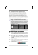
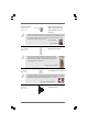
Chassis, NB and Power Fan Connectors Please connect the fan cables
(4-pin CHA_FAN1) to the fan connectors and
(see p.11 No. 16) match the black wire to the
(3-pin CHA_FAN2)
(see p.11 No. 15)
(3-pin PWR_FAN1)
(see p.11 No. 39)
(3-pin NB_FAN1)
(see p.11 No. 9)
GND
+12 V
C HA_FAN_SPEED
GND
+12V
PWR_FAN_SPEED
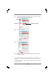
+ 5 V
DUMMY
DUMMY
SPEAKER
1
Chassis Speaker Header Please connect the chassis
(4-pin SPEAKER 1) speaker to this header.
(see p.11 No. 17)
GND
PWRBTN#
PLED-
PLED+
DUMMY
RESET#
GND
HDLED+
HDLED-
1
System Panel Header This header accommodates
(9-pin PANEL1) several system front panel
(see p.11 No. 14) functions.
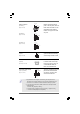
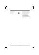
Power LED Header Please connect the chassis
(3-pin PLED1) power LED to this header to
(see p.11 No. 22) indicate system power status.
The LED is on when the system
is operating. The LED keeps
blinking in S1 state. The LED is
off in S3/S4 state or S5 state
(power off).
1
PLED+
PLED+
PLED-
GND
+12V
NB_FAN_SPEED
FAN_SPEED_CONTROL
GND
+12V
CHA_FAN_SPEED
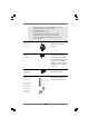
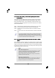
D. MIC_RET and OUT_RET are for HD audio panel only. You don’t
need to connect them for AC’97 audio panel.
E. To activate the front mic.
For Windows
®
XP / XP 64-bit OS:
Select “Mixer”. Select “Recorder”. Then click “FrontMic”.
For Windows
®
7 / 7 64-bit / Vista
TM
/ Vista
TM
64-bit OS:
Go to the "FrontMic" Tab in the Realtek Control panel. Adjust
“Recording Volume”.