890GX Extreme4 User Manual Version 1.0 Published July 2010 Copyright©2010 ASRock INC. All rights reserved.
Copyright Notice: No part of this manual may be reproduced, transcribed, transmitted, or translated in any language, in any form or by any means, except duplication of documentation by the purchaser for backup purpose, without written consent of ASRock Inc. Products and corporate names appearing in this manual may or may not be registered trademarks or copyrights of their respective companies, and are used only for identification or explanation and to the owners’ benefit, without intent to infringe.
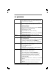
Contents 1 . Introduction ............................................................ 5 1.1 1.2 1.3 1.4 Package Contents ..................................................................... Specifications ............................................................................ Motherboard Layout ................................................................. I/O Panel .................................................................................... 5 6 12 13 2 . Installation ..................
3 . BIOS SSETUP ETUP UTILITY ................................................... 48 3.1 3.2 3.3 3.4 3.5 3.6 3.7 3.8 Introduction ............................................................................... 3.1.1 BIOS Menu Bar ............................................................... 3.1.2 Navigation Keys ............................................................. Main Screen .............................................................................. OC Tweaker Screen .......................
1. Introduction Thank you for purchasing ASRock 890GX Extreme4 motherboard, a reliable motherboard produced under ASRock’s consistently stringent quality control. It delivers excellent performance with robust design conforming to ASRock’s commitment to quality and endurance. In this manual, chapter 1 and 2 contain introduction of the motherboard and step-by-step guide to the hardware installation. Chapter 3 and 4 contain the configuration guide to BIOS setup and information of the Support CD.
1.2 Specifications Platform CPU Chipset Memory Expansion Slot Graphics - ATX Form Factor: 12.0-in x 9.6-in, 30.5 cm x 24.
Audio LAN Rear Panel I/O SATA3 USB 3.0 Connector - Supports Full HD 1080p Blu-ray (BD) / HD-DVD playback with DVI and HDMI ports - 7.1 CH HD Audio with Content Protection (Realtek ALC892 Audio Codec) - Premium Blu-ray audio support - Supports THX TruStudio ProTM - PCIE x1 Gigabit LAN 10/100/1000 Mb/s - Realtek RTL8111E - Supports Wake-On-LAN - Supports LAN Cable Detection - Supports Energy Efficient Ethernet 802.
Smart Switch BIOS Feature Support CD Unique Feature Hardware Monitor OS Certifications - 3 x USB 2.0 headers (support 6 USB 2.0 ports) - 1 x USB 3.0 header (supports 2 USB 3.0 ports) - 1 x Dr. Debug (7-Segment Debug LED) - 1 x Clear CMOS Switch with LED - 1 x Power Switch with LED - 1 x Reset Switch with LED - 8Mb AMI BIOS - AMI Legal BIOS - Supports “Plug and Play” - ACPI 1.1 Compliance Wake Up Events - Supports jumperfree - SMBIOS 2.3.
WARNING Please realize that there is a certain risk involved with overclocking, including adjusting the setting in the BIOS, applying Untied Overclocking Technology, or using the thirdparty overclocking tools. Overclocking may affect your system stability, or even cause damage to the components and devices of your system. It should be done at your own risk and expense. We are not responsible for possible damage caused by overclocking. CAUTION! 1.
9. Featuring an advanced proprietary hardware and software design, Intelligent Energy Saver is a revolutionary technology that delivers unparalleled power savings. The voltage regulator can reduce the number of output phases to improve efficiency when the CPU cores are idle. In other words, it is able to provide exceptional power saving and improve power efficiency without sacrificing computing performance.
13. If you desire a faster, less restricted way of charging your Apple devices, such as iPhone/iPod/iPad Touch, ASRock has prepared a wonderful solution for you - ASRock APP Charger. Simply installing the APP Charger driver, it makes your iPhone charged much quickly from your computer and up to 40% faster than before.
1.3 Motherboard Layout 3 2 1 4 5 CPU_FAN1 CPU_FAN2 6 7 24.4cm (9.6-in) LAN PHY PCIE1 41 CHA_FAN1 10 CHA_FAN2 FSB800 DDR3_B2 (64 bit, 240-pin module) DDR3_A2 (64 bit, 240-pin module) DDR3_B1 (64 bit, 240-pin module) 9 11 30.5cm (12.0-in) 42 AMD 890GX Chipset 8 CHA_FAN3 Center: FRONT Bottom: MIC IN Top: LINE IN Bottom: Optical SPDIF Center: REAR SPK Top: CTR BASS PWR_FAN1 RJ-45 LAN eSATA3 IEEE 1394 Dual Channel DDR3 1866 Clr CMOS 43 FSB2.
1.4 I/O PPanel anel 1 17 1 2 3 *4 5 6 7 8 ** 9 2 3 15 16 4 13 12 14 USB 2.0 Ports (USB45) VGA/D-Sub Port USB 2.0 Ports (USB23) LAN RJ-45 Port Central / Bass (Orange) Rear Speaker (Black) Optical SPDIF Out Port Line In (Light Blue) Front Speaker (Lime) 10 11 12 *** 13 14 15 16 17 5 8 6 9 7 10 11 Microphone (Pink) USB 3.
To enable Multi-Streaming function, you need to connect a front panel audio cable to the front panel audio header. After restarting your computer, you will find “Mixer” tool on your system. Please select “Mixer ToolBox” , click “Enable playback multi-streaming”, and click “ok”. Choose “2CH”, “4CH”, “6CH”, or “8CH” and then you are allowed to select “Realtek HDA Primary output” to use Rear Speaker, Central/Bass, and Front Speaker, or select “Realtek HDA Audio 2nd output” to use front panel audio.
2. Installation This is an ATX form factor (12.0-in x 9.6-in, 30.5 cm x 24.4 cm) motherboard. Before you install the motherboard, study the configuration of your chassis to ensure that the motherboard fits into it. Pre-installation Precautions Take note of the following precautions before you install motherboard components or change any motherboard settings. Before you install or remove any component, ensure that the power is switched off or the power cord is detached from the power supply.
2.1 CPU Installation Step 1. Step 2. Step 3. o Unlock the socket by lifting the lever up to a 90 angle. Position the CPU directly above the socket such that the CPU corner with the golden triangle matches the socket corner with a small triangle. Carefully insert the CPU into the socket until it fits in place. The CPU fits only in one correct orientation. DO NOT force the CPU into the socket to avoid bending of the pins. Step 4.
2.3 Installation of Memory Modules (DIMM) This motherboard provides four 240-pin DDR3 (Double Data Rate 3) DIMM slots, and supports Dual Channel Memory Technology. For dual channel configuration, you always need to install identical (the same brand, speed, size and chiptype) DDR3 DIMM pair in the slots of the same color. In other words, you have to install identical DDR3 DIMM pair in Dual Channel A (DDR3_A1 and DDR3_B1; Blue slots; see p.12 No.
Installing a DIMM Please make sure to disconnect power supply before adding or removing DIMMs or the system components. Step 1. Step 2. Unlock a DIMM slot by pressing the retaining clips outward. Align a DIMM on the slot such that the notch on the DIMM matches the break on the slot. notch break notch break The DIMM only fits in one correct orientation. It will cause permanent damage to the motherboard and the DIMM if you force the DIMM into the slot at incorrect orientation. Step 3.
2.4 Expansion Slots (PCI and PCI Express Slots) There are 3 PCI slots and 4 PCI Express slots on this motherboard. PCI Slots: PCI slots are used to install expansion cards that have the 32-bit PCI interface. PCIE Slots: PCIE1 (PCIE x1 slot; White) is used for PCI Express cards with x1 lane width cards, such as Gigabit LAN card and SATA2 card.
2.5 Dual Monitor and Surround Display Features Dual Monitor Feature This motherboard supports dual monitor feature. With the internal VGA output support (DVI-D, D-Sub and HDMI), you can easily enjoy the benefits of dual monitor feature without installing any add-on VGA card to this motherboard. This motherboard also provides independent display controllers for DVI-D, D-Sub and HDMI to support dual VGA output so that DVI-D, D-sub and HDMI can drive same or different display contents.
Surround Display Feature This motherboard supports surround display upgrade. With the internal VGA output support (DVI-D, D-Sub and HDMI) and external add-on PCI Express VGA cards, you can easily enjoy the benefits of surround display feature. Please refer to the following steps to set up a surround display environment: 1. Install the ATITM PCI Express VGA cards on PCIE2, PCIE3 and PCIE4 slots. Please refer to page 19 for proper expansion card installation procedures for details. 2.
For Windows® 7 / 7 64-bit / VistaTM / VistaTM 64-bit OS: Right click the desktop, choose “Personalize”, and select the “Display Settings” tab so that you can adjust the parameters of the multi-monitor according to the steps below. A. Click the number ”2” icon. B. Click the items “This is my main monitor” and “Extend the desktop onto this monitor”. C. Click “OK” to save your change. D. Repeat steps A through C for the display icon identified by the number three, four, five, six, seven and eight. 6.
2.6 CrossF ireX TM, 3W ay CrossF ireX TM and Quad CrossFireX 3-W CrossFireX CrossFireX TM Operation Guide This motherboard supports CrossFireXTM, 3-way CrossFireXTM and Quad CrossFireXTM feature. CrossFireXTM technology offers the most advantageous means available of combining multiple high performance Graphics Processing Units (GPU) in a single PC.
Step 2. Connect two Radeon graphics cards by installing CrossFire Bridge on CrossFire Bridge Interconnects on the top of Radeon graphics cards. (CrossFire Bridge is provided with the graphics card you purchase, not bundled with this motherboard. Please refer to your graphics card vendor for details.) CrossFire Bridge or Step 3. Connect the DVI monitor cable to the DVI connector on the Radeon graphics card on PCIE2 slot.
2.6.1.2 Installing Three CrossFireX TM-Ready Graphics Cards Step 1. Install one Radeon graphics card to PCIE2 slot. For the proper installation procedures, please refer to section “Expansion Slots”. Step 2. Install one Radeon graphics card to PCIE3 slot. For the proper installation procedures, please refer to section “Expansion Slots”. Step 3. Install one Radeon graphics card to PCIE4 slot. For the proper installation procedures, please refer to section “Expansion Slots”. Step 4.
CrossFireTM Bridge Step 5. Connect the DVI monitor cable to the DVI connector on the Radeon graphics card on PCIE2 slot. (You may use the DVI to D-Sub adapter to convert the DVI connector to D-Sub interface, and then connect the D-Sub monitor cable to the DVI to D-Sub adapter.
2.6.2 Driver Installation and Setup Step 1. Step 2. Power on your computer and boot into OS. Remove the ATITM driver if you have any VGA driver installed in your system. The Catalyst Uninstaller is an optional download. We recommend using this utility to uninstall any previously installed Catalyst drivers prior to installation. Please check AMD website for ATITM driver updates. Step 3. Step 4. Step 5. Install the required drivers to your system. For Windows® XP OS: A.
Although you have selected the option “Enable CrossFireTM”, the CrossFireXTM function may not work actually. Your computer will automatically reboot. After restarting your computer, please confirm whether the option “Enable CrossFireTM” in “ATI Catalyst Control Center” is selected or not; if not, please select it again, and then you are able to enjoy the benefit of CrossFireXTM feature. Step 7. You can freely enjoy the benefit of CrossFireXTM, 3-Way CrossFireXTM or Quad CrossFireXTM feature.
2.7 ATI TM Hybrid CrossF ireX TM Operation Guide CrossFireX This motherboard supports ATITM Hybrid CrossFireXTM feature. ATITM Hybrid CrossFireXTM brings multi-GPU performance capabilities by enabling an AMD 890GX integrated graphics processor and a discrete graphics processor to operate simultaneously with combined output to a single display for blisteringlyfast frame rates.
Step 7. Double-click “ATI Catalyst Control Center”. Click “View”, click “CrossFireTM”, and then select the option “Enable CrossFireTM”. View Enable CrossFireTM CrossFireTM Step 8. Click “Yes” to continue. Step 9. Click “OK” to save your change. Step 10. Reboot your system. Then you can freely enjoy the benefit of HybridTM CrossFireXTM feature. * Hybrid CrossFireXTM appearing here is a registered trademark of ATITM Technologies Inc.
2.8 Jumpers Setup The illustration shows how jumpers are setup. When the jumper cap is placed on pins, the jumper is “Short”. If no jumper cap is placed on pins, the jumper is “Open”. The illustration shows a 3-pin jumper whose pin1 and pin2 are “Short” when jumper cap is placed on these 2 pins. Jumper Clear CMOS Jumper (CLRCMOS1) (see p.12, No. 25) Setting 1_2 Default 2_3 Clear CMOS Note: CLRCMOS1 allows you to clear the data in CMOS.
2.9 Onboard Headers and Connectors Onboard headers and connectors are NOT jumpers. Do NOT place jumper caps over these headers and connectors. Placing jumper caps over the headers and connectors will cause permanent damage of the SATA3 (PORT 2) SATA4 (PORT 3) Serial ATA3 Connectors (SATA1 (PORT 0): see p.12, No. 20) (SATA3 (PORT 2): see p.12, No. 21) (SATA4 (PORT 3): see p.12, No. 17) (SATA5 (PORT 4): see p.12, No. 18) SATA1 (PORT 0) SATA2 (PORT 1) (SATA2 (PORT 1): see p.12, No.
USB 3.0 Header IntA_P2_D+ IntA_P2_DGND IntA_P2_SSTX+ IntA_P2_SSTXGND IntA_P2_SSRX+ IntA_P2_SSRXVbus (19-pin USB3_2_3) (see p.12 No. 24) 1 ID Besides two default USB 3.0 ports on the I/O panel, there is one USB 3.0 header on this motherboard. This USB 3.0 header can support two USB 3.0 ports. Vbus IntA_P1_SSRXIntA_P1_SSRX+ GND IntA_P1_SSTXIntA_P1_SSTX+ GND IntA_P1_DIntA_P1_D+ Infrared Module Header IRTX +5V DUMMY (5-pin IR1) (see p.12 No.
Connect the power switch, reset switch and system status indicator on the chassis to this header according to the pin assignments below. Note the positive and negative pins before connecting the cables. PWRBTN (Power Switch): Connect to the power switch on the chassis front panel. You may configure the way to turn off your system using the power switch. RESET (Reset Switch): Connect to the reset switch on the chassis front panel.
Chassis and Power Fan Connectors (4-pin CHA_FAN1) (see p.12 No. 8) (3-pin CHA_FAN2) (see p.12 No. 10) (3-pin CHA_FAN3) (see p.12 No. 11) GND +12V CHA_FAN_SPEED FAN_SPEED_CONTROL GND +12V CHA_FAN_SPEED Please connect the fan cables to the fan connectors and match the black wire to the ground pin. CHA_FAN1/2/3 fan speed can be controlled through BIOS or OC Tuner utility. GND +12V CHA_FAN_SPEED (3-pin PWR_FAN1) (see p.12 No.
ATX 12V Power Connector 8 5 (8-pin ATX12V1) 4 1 Please connect an ATX 12V power supply to this connector. (see p.12 No. 1) Though this motherboard provides 8-pin ATX 12V power connector, it can still work if you adopt a traditional 4-pin ATX 12V power supply. To use the 4-pin ATX power supply, please plug your power supply along with Pin 1 and Pin 5. 8 5 4-Pin ATX 12V Power Supply Installation IEEE 1394 Header RXTPAM_0 GND RXTPBM_0 +12V GND (9-pin FRONT_1394) (see p.12 No.
2.10 Smart Switches This motherboard has three smart switches: power switch, reset switch and clear CMOS switch, allowing users to quickly turn on/off or reset the system or clear the CMOS values. Power Switch Power Switch is a smart switch, allowing users to quickly turn on/off the system. (PWRBTN) (see p.12 No. 28) Reset Switch (RSTBTN) (see p.12 No. 27) Reset Switch is a smart switch, allowing users to quickly reset the system.
2.11 Dr. Debug Dr. Debug is used to provide code information, which makes troubleshooting even easier. Please see the diagrams below for reading the Dr. Debug codes. The Bootblock initialization code sets up the chipset, memory and other components before system memory is available. The following table describes the type of checkpoints that may occur during the bootblock initialization portion of the BIOS: Checkpoint Before D1 Description Early chipset initialization is done.
The POST code checkpoints are the largest set of checkpoints during the BIOS pre-boot process. The following table describes the type of checkpoints that may occur during the POST portion of the BIOS: Checkpoint 03 Description Disable NMI, Parity, video for EGA, and DMA controllers. Initialize BIOS, POST, Runtime data area. Also initialize BIOS modules on POST entry and GPNV area. Initialized CMOS as mentioned in the Kernel Variable 04 “wCMOSFlags.
33 Initializes the silent boot module. Set the window for displaying text 37 information. Displaying sign-on message, CPU information, setup key message, and 38 any OEM specific information. Initializes different devices through DIM. 39 3A Initializes DMAC-1 & DMAC-2. Initialize RTC date/time. 3B Test for total memory installed in the system. Also, Check for DEL or ESC keys to limit memory test. Display total memory in the system. 3C 40 Mid POST initialization of chipset registers.
2.12 Serial A ATTA3 (SA (SATTA3) Hard Disks Installation This motherboard adopts AMD SB850 chipset that supports Serial ATA3 (SATA3) hard disks and RAID functions. You may install SATA3 hard disks on this motherboard for internal storage devices. This section will guide you to install the SATA3 hard disks. STEP 1: Install the SATA3 hard disks into the drive bays of your chassis. STEP 2: Connect the SATA power cable to the SATA3 hard disk.
2.14 SA eature and Operation Guide SATTA3 HDD Hot Plug FFeature This motherboard supports Hot Plug feature for SATA3 HDD in RAID / AHCI mode. Please read below operation guide of Hot Plug feature carefully. Before you process the SATA3 HDD Hot Plug, please check below cable accessories from the motherboard gift box pack. A. 7-pin SATA data cable B. SATA power cable with SATA 15-pin power connector interface A. SATA data cable (Red) SATA 7-pin connector B.
How to Hot Plug a SATA3 HDD: Points of attention, before you process the Hot Plug: Please do follow below instruction sequence to process the Hot Plug, improper procedure will cause the SATA3 HDD damage and data loss. Step 1 Please connect SATA power cable 1x4-pin end Step 2 Connect SATA data cable to the motherboard’s SATA3 connector. (White) to the power supply 1x4-pin cable. SATA power cable 1x4-pin power connector (White) Step 3 Connect SATA 15-pin power cable connector (Black) end to SATA3 HDD.
2.15 Driver Installation Guide To install the drivers to your system, please insert the support CD to your optical drive first. Then, the drivers compatible to your system can be auto-detected and listed on the support CD driver page. Please follow the order from up to bottom side to install those required drivers. Therefore, the drivers you install can work properly. 2.
STEP 3: Use “RAID Installation Guide” to set RAID configuration. Before you start to configure RAID function, you need to check the RAID installation guide in the Support CD for proper configuration. Please refer to the BIOS RAID installation guide part of the document in the following path in the Support CD: .. \ RAID Installation Guide STEP 4: Install Windows® XP / XP 64-bit OS on your system. After step 1, 2, 3, you can start to install Windows® XP / XP 64-bit OS on your system.
2.17 Installing Windows ® 7 / 7 64-bit / Vista TM / Vista TM 64-bit / XP / XP 64-bit Without RAID Functions If you want to install Windows® 7 / 7 64-bit / VistaTM / VistaTM 64-bit / XP / XP 64-bit OS on your SATA3 HDDs without RAID functions, please follow below procedures according to the OS you install. 2.17.1 Installing Windows ® XP / XP 64-bit Without RAID Functions If you want to install Windows® XP / XP 64-bit on your SATA3 HDDs without RAID functions, please follow below steps.
2.17.2 Installing Windows ® 7 / 7 64-bit / Vista TM / Vista TM 64-bit Without RAID Functions If you want to install Windows® 7 / 7 64-bit / VistaTM / VistaTM 64-bit on your SATA3 HDDs without RAID functions, please follow below steps. Using SATA3 HDDs with NCQ and Hot Plug functions (AHCI mode) STEP 1: Set Up BIOS. A. Enter BIOS SETUP UTILITY Advanced screen Storage Configuration. B. Set the “SATA Operation Mode” option to [AHCI].
3. BIOS SETUP UTILITY 3.1 Introduction This section explains how to use the BIOS SETUP UTILITY to configure your system. The SPI Memory on the motherboard stores the BIOS SETUP UTILITY. You may run the BIOS SETUP UTILITY when you start up the computer. Please press or during the Power-On-Self-Test (POST) to enter the BIOS SETUP UTILITY, otherwise, POST will continue with its test routines.
3.1.2 Navigation Keys Please check the following table for the function description of each navigation key. Navigation Key(s) / / + / 3.
3.3 OC TTweak weak er Screen weaker In the OC Tweaker screen, you can set up overclocking features.
Spread Spectrum This item should always be [Auto] for better system stability. Boot Failure Guard Enable or disable the feature of Boot Failure Guard. Boot Failure Guard Count Enable or disable the feature of Boot Failure Guard Count. ASRock UCC ASRock UCC (Unlock CPU Core) feature simplifies AMD CPU activation. As long as a simple switch of the BIOS option “ASRock UCC”, you can unlock the extra CPU core to enjoy an instant performance boost.
CPU Frequency Multiplier For safety and system stability, it is not recommended to adjust the value of this item. CPU Voltage It allows you to adjust the value of CPU voltage. However, for safety and system stability, it is not recommended to adjust the value of this item. NB Frequency Multiplier For safety and system stability, it is not recommended to adjust the value of this item. NB Voltage It allows you to adjust the value of NB voltage.
Memory Timing BIOS SETUP UTILITY OC Tweaker Memory Timing Memory Controller Mode Power Down Enable Bank Interleaving Channel Interleaving [Unganged] [Disabled] [Auto] [HASH 2] CAS Latency (CL) TRCD TRP TRAS TRTP TRRD TWTR TWR TRC TRWTWB TRWTTO TWRRD [Auto] [Auto] [Auto] [Auto] [Auto] [Auto] [Auto] [Auto] [Auto] [Auto] [Auto] [Auto] 9 12 12 30 5 4 5 10 33 8 7 2 +F1 F9 F10 ESC Select Screen Select Item Change Option General Help Load Defaults Save and Exit Exit v02.
TRRD Use this to adjust TRRD values. Configuration options: [Auto], [4CLK] to [7CLK]. The default value is [Auto]. TWTR Use this to adjust TWTR values. Configuration options: [Auto], [4CLK] to [7CLK]. The default value is [Auto]. TWR Use this to adjust TWR values. Configuration options: [Auto], [5CLK] to [12CLK]. The default value is [Auto]. TRC Use this to adjust TRC values. Configuration options: [Auto], [11CLK] to [42CLK]. The default value is [Auto]. TRWTWB Use this to adjust TRWTWB values.
CHA ADDR/CMD Setup Use this to adjust values for CHA ADDR/CMD Setup feature. Configuration options: [Auto], [1/2CLK] and [1CLK]. The default value is [Auto]. CHA CS/ODT Delay Use this to adjust values for CHA CS/ODT Delay feature. Configuration options: [Auto], [No Delay], [1/64CLK] to [31/64CLK]. The default value is [Auto]. CHA CS/ODT Setup Use this to adjust values for CHA CS/ODT Setup feature. Configuration options: [Auto], [1/2CLK] and [1CLK]. The default value is [Auto].
CHA Processor ODT Use this to adjust values for CHA Processor ODT. Configuration options: [Auto], [240 ohms], [120 ohms] and [60 ohms]. The default value is [Auto]. CHB CKE Drive Use this to adjust values for CHB CKE Drive. Configuration options: [Auto], [1.00x], [1.25x], [1.50x] and [2.00x]. The default value is [Auto]. CHB CS/ODT Drive Use this to adjust values for CHB CS/ODT Drive. Configuration options: [Auto], [1.00x], [1.25x], [1.50x] and [2.00x]. The default value is [Auto].
Chipset Settings SidePort Clock Speed This allows you to select sideport clock speed. The default value is [Auto]. Configuration options: [Auto], [533MHz] to [1700MHz]. Onboard GPU Clock Override This allows you to enable or disable the Onboard GPU Clock Override feature. Onboard GPU Clock This option only appears when you enable “Onboard GPU Clock Override”. The default value is [700]. HT Voltage Use this to select Hyper-Transport voltage. Configuration options: [Auto], [1.106V] to [1.820V].
3.4 Advanced Screen In this section, you may set the configurations for the following items: CPU Configuration, Chipset Configuration, ACPI Configuration, Storage Configuration, PCIPnP Configuration, SuperIO Configuration, and USB Configuration. Main BIOS SETUP UTILITY Boot OC Tweaker Advanced H/W Monitor Advanced Settings Security Exit Options for CPU WARNING : Setting wrong values in below sections may cause system to malfunction.
3.4.1 CPU Configuration BIOS SETUP UTILITY Advanced Enabling this function may reduce CPU voltage and memory freq., and lead to system stability or compatibility issue with some memory modules or power supplies. Please set this item to [Disabled] if above issue occurs.
3.4.2 Chipset Configuration BIOS SETUP UTILITY Advanced Chipset Settings Options Onboard 80 Port LED [Auto] Onboard HD Audio Front Panel [Auto] [Auto] Onboard Lan Energy Efficient Ethernet Dr.
Share Memory This allows you to set share memory feature. The default value is [Auto]. Configuration options: [Auto], [32MB], [64MB], [128MB], [256MB] and [512MB]. Onboard HDMI HD Audio This allows you to enable or disable the onboard HDMI HD Audio in AMD 890GX. If you use Dual-link DVI monitor, please set this item to [Disabled]. Surround View This allows you to enable or disable the Surround View feature or Hybrid CrossFireX TM feature.
3.4.3 ACPI Configuration BIOS SETUP UTILITY Advanced ACPI Settings Suspend To RAM Check Ready Bit Away Mode Support [Auto] [Auto] [Disabled] Restore on AC / Power Loss Ring-In Power On PCI Devices Power On PS / 2 Keyboard Power On RTC Alarm Power On [Power Off] [Disabled] [Disabled] [Disabled] [Disabled] ACPI HPET Table [Disabled] Select auto-detect or disable the STR feature. +F1 F9 F10 ESC Select Screen Select Item Change Option General Help Load Defaults Save and Exit Exit v02.
3.4.4 Storage Configuration BIOS SETUP UTILITY Advanced Configure onboard serial ATA controller. Storage Configuration Onboard SATA Controller SATA Operation Mode SATA IDE Combined Mode SATA3_6 Mode SATA3_1 SATA3_2 SATA3_3 SATA3_4 SATA3_5 SATA3_6 [Enabled] [IDE] [Enabled] [Gen2] [Hard Disk] [Not Detected] [Not Detected] [Not Detected] [Not Detected] [Not Detected] +F1 F9 F10 ESC Select Screen Select Item Change Option General Help Load Defaults Save and Exit Exit v02.
BIOS SETUP UTILITY Advanced SATA3_1 Master Device Vendor Size LBA Mode Block Mode PIO Mode Async DMA Ultra DMA S.M.A.R.T. Select the type of device connected to the system. :Hard Disk :MAXTOR 6L080J4 :80.0 GB :Supported :16Sectors :4 :MultiWord DMA-2 :Ultra DMA-6 :Supported Type LBA/Large Mode Block (Multi-Sector Transfer) PIO Mode DMA Mode S.M.A.R.T.
S.M.A.R.T. Use this item to enable or disable the S.M.A.R.T. (Self-Monitoring, Analysis, and Reporting Technology) feature. Configuration options: [Disabled], [Auto], [Enabled]. 32Bit Data Transfer Use this item to enable 32-bit access to maximize the IDE hard disk data transfer rate. 3.4.5 PCIPnP Configuration BIOS SETUP UTILITY Advanced Value in units of PCI clocks for PCI device latency timer register.
3.4.6 Super IO Configuration BIOS SETUP UTILITY Advanced Configure Super IO Chipset Serial Port Address Infrared Port Address PS/2 Port Type Allow BIOS to Select Serial Port Base Addresses. [3F8 / IRQ4] [Disabled] [Auto] +F1 F9 F10 ESC Select Screen Select Item Change Option General Help Load Defaults Save and Exit Exit v02.54 (C) Copyright 1985-2003, American Megatrends, Inc. Serial Port Address Use this item to set the address for the onboard serial port or disable it.
3.4.7 USB Configuration BIOS SETUP UTILITY Advanced USB Configuration USB Controller Legacy USB Support USB 3.0 Controller [Enabled] [Enabled] [Enabled] USB Keyboard/Remote Power On USB Mouse Power On [Disabled] [Disabled] To enable or disable the onboard USB controllers. +F1 F9 F10 ESC Select Screen Select Item Change Option General Help Load Defaults Save and Exit Exit v02.54 (C) Copyright 1985-2003, American Megatrends, Inc.
3.5 Hardware Health Event Monitoring Screen In this section, it allows you to monitor the status of the hardware on your system, including the parameters of the CPU temperature, motherboard temperature, CPU fan speed, chassis fan speed, and the critical voltage.
3.6 Boot Screen In this section, it will display the available devices on your system for you to configure the boot settings and the boot priority. Main OC Tweaker BIOS SETUP UTILITY Advanced H/W Monitor Boot Boot Settings Exit Configure Settings during System Boot.
Boot From Onboard LAN Use this item to enable or disable the Boot From Onboard LAN feature. Boot Up Num-Lock If this item is set to [On], it will automatically activate the Numeric Lock function after boot-up. 3 . 7 Security Screen In this section, you may set or change the supervisor/user password for the system. For the user password, you may also clear it.
3.8 Exit Screen Main OC Tweaker BIOS SETUP UTILITY Advanced H/W Monitor Boot Exit Options Security Exit Exit system setup after saving the changes. Save Changes and Exit Discard Changes and Exit Discard Changes F10 key can be used for this operation. Load BIOS Defaults Load Performance Setup Default Load Power Saving Setup Default Enter F1 F9 F10 ESC Select Screen Select Item Go to Sub Screen General Help Load Defaults Save and Exit Exit v02.54 (C) Copyright 1985-2005, American Megatrends, Inc.
Software Supportt 4. Sof tware Suppor 4.1 Install Operating System This motherboard supports various Microsoft® Windows® operating systems: 7 / 7 64-bit / VistaTM / VistaTM 64-bit / XP / XP 64-bit. Because motherboard settings and hardware options vary, use the setup procedures in this chapter for general reference only. Refer to your OS documentation for more information. 4.