939Dual-SATA2 User Manual Version 1.1 Published July 2006 Copyright©2006 ASRock INC. All rights reserved.
Copyright Notice: No part of this manual may be reproduced, transcribed, transmitted, or translated in any language, in any form or by any means, except duplication of documentation by the purchaser for backup purpose, without written consent of ASRock Inc. Products and corporate names appearing in this manual may or may not be registered trademarks or copyrights of their respective companies, and are used only for identification or explanation and to the owners’ benefit, without intent to infringe.
Contents 1 . Introduction ............................................................ 5 1.1 1.2 1.3 1.4 Package Contents ..................................................................... Specifications ........................................................................... Motherboard Layout ................................................................. ASRock 8CH I/O ........................................................................ 5 6 8 9 2 . Installation ............................
3.6 3.7 Security Screen ........................................................................ 37 Exit Screen ............................................................................... 38 4 . Software Support ................................................... 39 4.1 4.2 Install Operating System ........................................................... Support CD Information ............................................................. 4.2.1 Running Support CD ...................................
1. Introduction Thank you for purchasing ASRock 939Dual-SATA2 motherboard, a reliable motherboard produced under ASRock’s consistently stringent quality control. It delivers excellent performance with robust design conforming to ASRock’s commitment to quality and endurance. In this manual, chapter 1 and 2 contain introduction of the motherboard and step-bystep guide to the hardware installation. Chapter 3 and 4 contain the configuration guide to BIOS setup and information of the Support CD.
1.2 Specifications ATX Form Factor: 12.0-in x 9.6-in, 30.5 cm x 24.4 cm 939-Pin Socket Supporting AMD AthlonTM 64 / 64FX Processor Supports AMD’s Cool ‘n’ QuietTM Technology (see CAUTION 1) Chipsets: North Bridge: ULi® M1695 chipset For 939-Pin CPU, FSB @ 1 GHz / 2.0 GT/s South Bridge: ULi® M1567 chipset, supports SATA 1.5Gb/s Memory: 4 x DDR DIMM Slots: 4 DIMMs support PC3200 (DDR 400) / PC2700 (DDR 333) / PC2100 (DDR 266), Max.
ASRock 8CH I/O: BIOS: OS: 1 PS/2 Mouse Port, 1 PS/2 Keyboard Port 1 Serial Port: COM1 1 Parallel Port (ECP/EPP Support) 4 Ready-to-Use USB 2.0 Ports 1 RJ-45 Port Audio Jack: Side Speaker / Rear Speaker / Central/Bass / Line In / Front Speaker / Microphone (see CAUTION 6) AMI Legal BIOS Supports “Plug and Play” ACPI 1.1 Compliance Wake Up Events SMBIOS 2.3.
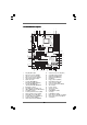
1.3 Motherboard Layout 2 1 5 4 3 7 6 8 24.4cm (9.6-in) PS2_USB_PWR1 CPU_FAN1 Center: SIDE SPK Bottom: CTR BASS Top: REAR SPK 1 1 1 1 J3 J4 37 J7 J8 1 1 J5 J6 Center: FRONT Top: LINE IN Bottom: MIC IN ULi M1695 Chipset 1 1 J1 J2 7.1CH CD1 36 35 FUTURE_CPU_PORT1 1 SATAII_1 PCIE 1 1 J10 1 J9 JMicron JMB360 PCIE 2 14 PCI 1 ATA133 AUDIO CODEC IDE1 2Mb BIOS USB2.
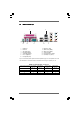
1.4 ASRock 8CH I/O 1 13 1 2 3 4 5 6 *7 2 11 12 10 Parallel Port RJ-45 Port Side Speaker (Gray) Rear Speaker (Black) Central / Bass (Orange) Line In (Light Blue) 8 9 10 11 12 13 3 6 4 7 5 8 9 Microphone (Pink) USB 2.0 Ports (USB01) USB 2.0 Ports (USB23) Serial Port: COM1 PS/2 Keyboard Port (Purple) PS/2 Mouse Port (Green) Front Speaker (Lime) * If you use 2-channel speaker, please connect the speaker’s plug into “Front Speaker Jack”.
2. Installation 939Dual-SATA2 is an ATX form factor (12.0-in x 9.6-in, 30.5 cm x 24.4 cm) motherboard. Before you install the motherboard, study the configuration of your chassis to ensure that the motherboard fits into it. Pre-installation Precautions Take note of the following precautions before you install motherboard components or change any motherboard settings. Before you install or remove any component, ensure that the power is switched off or the power cord is detached from the power supply.
2.1 CPU Installation Step 1. Step 2. Step 3. o Unlock the socket by lifting the lever up to a 90 angle. Position the CPU directly above the socket such that the CPU corner with the golden triangle matches the socket corner with a small triangle. Carefully insert the CPU into the socket until it fits in place. The CPU fits only in one correct orientation. DO NOT force the CPU into the socket to avoid bending of the pins. Step 4.
2.3 Installation of Memory Modules (DIMM) 939Dual-SATA2 motherboard provides four 184-pin DDR (Double Data Rate) DIMM slots, and supports Dual Channel Memory Technology. For dual channel configuration, you always need to install identical (the same brand, speed, size and chip-type) DDR DIMM pair in the slots of the same color. In other words, you have to install identical DDR DIMM pair in Dual Channel A (DDR1 and DDR2; Blue slots; see p.8 No.
Installing a DIMM Please make sure to disconnect power supply before adding or removing DIMMs or the system components. Step 1. Step 2. Unlock a DIMM slot by pressing the retaining clips outward. Align a DIMM on the slot such that the notch on the DIMM matches the break on the slot. notch break notch break The DIMM only fits in one correct orientation. It will cause permanent damage to the motherboard and the DIMM if you force the DIMM into the slot at incorrect orientation. Step 3.
2.4 Expansion Slots (Future CPU Port, PCI Slots, PCIE Slots, and AGP Slot) There are 1 Future CPU Port, 3 PCI slots, 2 PCIE slots, and 1 AGP slot on 939DualSATA2 motherboard. Future CPU Port (Yellow-Colored Port): Future CPU Port allows you to upgrade your AMD 939-Pin CPU to AMD 940-Pin CPU by installing an add-on ASRock M2CPU Board into this future CPU Port on 939DualSATA2 motherboard.
NOTE When adjusting the jumper settings, you may use the tool, Jumper Cap Remover, to help you removing the jumper caps more easily. This Jumper Cap Remover is bundled in your motherboard package, and please follow the “Jumper Cap Remover Instruction” to use it properly. PCI Slots: PCI slots are used to install expansion cards that have the 32-bit PCI interface. PCIE Slots: PCIE1 (PCIE x 16 slot) is used for PCI Express cards with x16 lane width graphics cards.
2.5 Surround Display Feature This motherboard supports Surround Display upgrade. With the external add-on PCI VGA card and PCI Express VGA card, you can easily enjoy the benefits of Surround Display feature. For the detailed instruction, please refer to the document at the following path in the Support CD: ..\ Surround Display 2.6 Jumpers Setup The illustration shows how jumpers are setup. When the jumper cap is placed on pins, the jumper is “Short”.
2.7 Onboard Headers and Connectors Onboard headers and connectors are NOT jumpers. Do NOT place jumper caps over these headers and connectors. Placing jumper caps over the headers and connectors will cause permanent damage of the motherboard! • Floppy Connector (33-pin FLOPPY1) (see p.8 No. 24) Pin1 FLOPPY1 the red-striped side to Pin1 Note: Make sure the red-striped side of the cable is plugged into Pin1 side of the connector.
Serial ATA (SATA) Power Cable (Optional) connect to the SATA HDD power connector connect to the power supply USB 2.0 Header USB_PWR P-6 P+6 GND DUMMY (9-pin USB67) (see p.8 No. 21) 1 GND P+7 P-7 USB_PWR USB 2.0 Header USB_PWR P-5 P+5 GND DUMMY (9-pin USB45) (see p.8 No. 22) 1 GND P+4 P-4 USB_PWR Infrared Module Header IRTX +5VSB DUMMY (5-pin IR1) (see p.8 No. 25) 1 GND IRRX Internal Audio Connectors (4-pin CD1) CD-R GND GND CD-L (CD1: see p.8 No.
System Panel Header PLED+ PLEDPWRBTN# GND (9-pin PANEL1) (see p.8 No. 17) 1 This header accommodates several system front panel functions. DUMMY RESET# GND HDLEDHDLED+ Chassis Speaker Header 1 (4-pin SPEAKER 1) SPEAKER DUMMY DUMMY +5V (see p.8 No. 18) Chassis Fan Connector (3-pin CHA_FAN1) (see p.8 No. 19) GND +12V CHA_FAN_SPEED CPU Fan Connector (3-pin CPU_FAN1) GND +12V CPU_FAN_SPEED (see p.8 No. 3) ATX Power Connector Please connect the chassis speaker to this header.
2.8 Serial A ATTA (SA (SATTA) Hard Disks Installation This motherboard adopts JMicron JMB360 chipset that supports Serial ATAII (SATAII) hard disk. It also adopts ULi M1567 south bridge chipset that supports Serial ATA (SATA) hard disks, and supports RAID functions. You may install SATA hard disks on this motherboard for internal storage devices. This section will guide you to install the SATA hard disks. STEP 1: Install the SATA hard disks into the drive bays of your chassis.
Once you have the SATA driver diskette ready, you may start to install Windows 2000 / Windows XP / Windows XP 64-bit on your system directly without setting the RAID configuration on your system, or you may start to use “RAID Installation Guide” to set RAID 0 / RAID 1 / JBOD configuration before you install the OS. Before you start to configure the RAID function, you need to check the installation guide in the Support CD for proper configuration.
3. BIOS SETUP UTILITY 3.1 Introduction This section explains how to use the BIOS SETUP UTILITY to configure your system. The Flash Memory on the motherboard stores the BIOS SETUP UTILITY. You may run the BIOS SETUP UTILITY when you start up the computer. Please press during the Power-On-Self-Test (POST) to enter the BIOS SETUP UTILITY, otherwise, POST will continue with its test routines.
3.1.2 Navigation Keys Please check the following table for the function description of each navigation key. Navigation Key(s) / / + / 3.
In the future, you may upgrade your AMD 939-Pin CPU to AMD 940-Pin (M2) CPU by installing an add-on ASRock M2CPU Board into future CPU Port on this motherboard 3.3 Advanced Screen In this section, you may set the configurations for the following items: CPU Configuration, Chipset Configuration, ACPI Configuration, IDE Configuration, PCIPnP Configuration, Floppy Configuration, SuperIO Configuration, and USB Configuration.
3.3.1 CPU Configuration BIOS SETUP UTILITY Advanced CPU Configuration If AUTO, multiplier and voltage will be left at the rated frequency/voltage. If Manual, multiplier and voltage will be set based on User Selection in Setup. Overclock Mode CPU Frequency (MHz) PCIE Frequency (MHz) Boot Failure Guard Spread Spectrum Cool' n' Quiet [Auto] [200] [100] [Enabled] [Auto] [Enabled] Processor Maximum Multiplier Processor Maximum Voltage Multiplier/Voltage Change x11 2200 MHz 1.
BIOS SETUP UTILITY Advanced CPU Configuration If AUTO, multiplier and voltage will be left at the rated frequency/voltage. If Manual, multiplier and voltage will be set based on User Selection in Setup. Overclock Mode CPU Frequency (MHz) PCIE Frequency (MHz) Boot Failure Guard Spread Spectrum Cool' n' Quiet [Auto] [200] [100] [Enabled] [Auto] [Enabled] Processor Maximum Multiplier Processor Maximum Voltage Multiplier/Voltage Change Processor Multiplier Processor Voltage x11 2200 MHz 1.
TRCD Use this to adjust TRCD values. Configuration options: [Auto], [2CLK], [3CLK], [4CLK], [5CLK], and [6CLK]. TRAS Use this to adjust TRAS values. Configuration options: [Auto], [5CLK], [6CLK], [7CLK], [8CLK], [9CLK], [10CLK], [11CLK], [12CLK], [13CLK], [14CLK], and [15CLK]. TRP Use this to adjust TRP values. Configuration options: [Auto], [2CLK], [3CLK], [4CLK], [5CLK], and [6CLK]. MA Timing Use this to adjust values for MA timing. Configuration options: [Auto], [2T], [1T]. The default value is [Auto].
Primary Graphics Adapter This item will switch the PCI Bus scanning order while searching for video card. It allows you to select the type of Primary VGA in case of multiple video controllers. The default value of this feature is [PCI]. Configuration options: [PCI], [PCIE] and [AGP]. CPU - NB Link Speed This feature allows you selecting CPU to NB link frequency. Configuration options: [Auto], [200 MHz], [400 MHz], [600 MHz], [800 MHz], and [1000 MHz].
Suspend to RAM Use this item to select whether to auto-detect or disable the Suspend-toRAM feature. Select [Auto] will enable this feature if the OS supports it. If you set this item to [Disabled], the function “Repost Video on STR Resume” will be hidden. Repost Video on STR Resume This feature allows you to repost video on STR resume. (STR refers to suspend to RAM.) Restore on AC/Power Loss This allows you to set the power state after an unexpected AC/power loss.
OnBoard IDE Controller You may enable either the primary IDE channel or the secondary IDE channel. Or you may enable both the primary and the secondary IDE channels by selecting [Both]. Set to [Disabled] will disable the both. Configuration options: [Disabled], [Primary], [Secondary], [Both]. OnBoard SATA Controller Enable the onboard SATA controller by selecting [Enabled]. The default value of this option is [Enabled]. Configuration options: [Enabled], [Disabled], [Auto].
BIOS SETUP UTILITY Advanced Primary IDE Master Device Vendor Size LBA Mode Block Mode PIO Mode Async DMA Ultra DMA S.M.A.R.T. Select the type of device connected to the system. :Hard Disk :MAXTOR 6L080J4 :80.0 GB :Supported :16Sectors :4 :MultiWord DMA-2 :Ultra DMA-6 :Supported Type LBA/Large Mode Block (Multi-Sector Transfer) PIO Mode DMA Mode S.M.A.R.T.
S.M.A.R.T. Use this item to enable or disable the S.M.A.R.T. (Self-Monitoring, Analysis, and Reporting Technology) feature. Configuration options: [Disabled], [Auto], [Enabled]. 32-Bit Data Transfer Use this item to enable 32-bit access to maximize the IDE hard disk data transfer rate. 3.3.5 PCIPnP Configuration BIOS SETUP UTILITY Advanced Advanced PCI / PnP Settings WARNING: Setting wrong values in below sections may cause system to malfunction.
3.3.6 Floppy Configuration In this section, you may configure the type of your floppy drive. BIOS SETUP UTILITY Advanced Floppy Configuration [1.44 MB 31 2"] [Disabled] Floppy A Floppy B Select the type of floppy drive connected to the system. +F1 F9 F10 ESC Select Screen Select Item Change Option General Help Load Defaults Save and Exit Exit v02.54 (C) Copyright 1985-2003, American Megatrends, Inc. 3.3.
Parallel Port Address Use this item to set the address for the onboard parallel port or disable it. Configuration options: [Disabled], [378], and [278]. Parallel Port Mode Use this item to set the operation mode of the parallel port. The default value is [ECP+EPP]. If this option is set to [ECP+EPP], it will show the EPP version in the following item, “EPP Version”. Configuration options: [Normal], [Bi-Directional], and [ECP+EPP]. EPP Version Use this item to set the EPP version. Configuration options: [1.
3.3.8 USB Configuration BIOS SETUP UTILITY Advanced USB Configuration USB Controller USB 2.0 Support Legacy USB Support To enable or disable the onboard USB controllers. [Enabled] [Enabled] [Disabled] +F1 F9 F10 ESC Select Screen Select Item Change Option General Help Load Defaults Save and Exit Exit v02.54 (C) Copyright 1985-2003, American Megatrends, Inc. USB Controller Use this item to enable or disable the use of USB controller. USB 2.0 Support Use this item to enable or disable the USB 2.
3.5 Boot Screen In this section, it will display the available devices on your system for you to configure the boot settings and the boot priority. Main Advanced BIOS SETUP UTILITY H/W Monitor Boot Boot Settings Exit Configure Settings during System Boot.
3.6 Security Screen In this section, you may set or change the supervisor/user password for the system. For the user password, you may also clear it. Main Advanced BIOS SETUP UTILITY H/W Monitor Boot Security Settings Supervisor Password User Password Security Exit Install or Change the password.
3.7 Exit Screen Main Advanced BIOS SETUP UTILITY H/W Monitro Boot Exit Options Security Exit Exit system setup after saving the changes. Save Changes and Exit Discard Changes and Exit Discard Changes F10 key can be used for this operation. Load Optimal Defaults Enter F1 F9 F10 ESC Select Screen Select Item Go to Sub Screen General Help Load Defaults Save and Exit Exit v02.54 (C) Copyright 1985-2003, American Megatrends, Inc.
4. Software Suppor Supportt 4.1 Install Operating System This motherboard supports various Microsoft® Windows® operating systems: 2000 / XP / XP 64-bit. Because motherboard settings and hardware options vary, use the setup procedures in this chapter for general reference only. Refer to your OS documentation for more information. 4.2 Support CD Information The Support CD that came with the motherboard contains necessary drivers and useful utilities that enhance the motherboard features. 4.2.
APPENDIX: echnology AMD’s Cool ‘n’ Quiet TM TTechnology For power-saving sake, it is strongly recommended to enable AMD’s Cool ‘n’ QuietTM technology under Windows system. When using this feature, please make sure to install “AMD Processor Driver” from the “Support CD” first. If you are using Windows 2000/XP operating system, please follow the instruction below to enable AMD’s Cool ‘n’ QuietTM technology: 1. 2. 3. 4. 5. 6. From the Windows 2000/XP operating system, click the Start button.