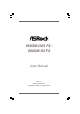
960GM-GS3 FX / 960GM-S3 FX User Manual Version 1.0 Published September 2011 Copyright©2011 ASRock INC. All rights reserved.
Copyright Notice: No part of this manual may be reproduced, transcribed, transmitted, or translated in any language, in any form or by any means, except duplication of documentation by the purchaser for backup purpose, without written consent of ASRock Inc. Products and corporate names appearing in this manual may or may not be registered trademarks or copyrights of their respective companies, and are used only for identification or explanation and to the owners’ benefit, without intent to infringe.
Contents 1 . Introduction ........................................................... 5 1.1 1.2 1.3 1.4 1.5 Package Contents ..................................................................... Specifications ........................................................................... Motherboard Layout (960GM-GS3 FX / 960GM-S3 FX) ............. I/O Panel (960GM-GS3 FX) ........................................................ I/O Panel (960GM-S3 FX) .........................................................
3 . BIOS SSETUP ETUP UTILITY ................................................... 34 3.1 3.2 3.3 3.4 3.5 3.6 3.7 3.8 Introduction ............................................................................... 3.1.1 BIOS Menu Bar ............................................................... 3.1.2 Navigation Keys ............................................................. Main Screen .............................................................................. OC Tweaker Screen .......................
1. Introduction Thank you for purchasing ASRock 960GM-GS3 FX / 960GM-S3 FX motherboard, a reliable motherboard produced under ASRock’s consistently stringent quality control. It delivers excellent performance with robust design conforming to ASRock’s commitment to quality and endurance. In this manual, chapter 1 and 2 contain introduction of the motherboard and step-bystep guide to the hardware installation. Chapter 3 and 4 contain the configuration guide to BIOS setup and information of the Support CD.
1.2 Specifications Platform CPU Chipset Memory Expansion Slot Graphics Audio LAN - Micro ATX Form Factor: 9.6-in x 7.2-in, 24.4 cm x 18.
Rear Panel I/O Connector BIOS Feature Support CD Unique Feature I/O Panel - 1 x PS/2 Mouse Port - 1 x PS/2 Keyboard Port - 1 x Serial Port: COM1 - 1 x VGA Port - 4 x Ready-to-Use USB 2.0 Ports - 1 x RJ-45 LAN Port with LED (ACT/LINK LED and SPEED LED) - HD Audio Jack: Line in / Front Speaker / Microphone - 4 x SATA2 3.
Hardware Monitor OS Certifications - Boot Failure Guard (B.F.G.) - CPU Temperature Sensing - Chassis Temperature Sensing - CPU/Chassis/Power Fan Tachometer - CPU Quiet Fan - Voltage Monitoring: +12V, +5V, +3.3V, Vcore - Microsoft® Windows® 7 / 7 64-bit / VistaTM / VistaTM 64-bit / XP / XP Media Center / XP 64-bit compliant - FCC, CE, WHQL - ErP/EuP Ready (ErP/EuP ready power supply is required) (see CAUTION 17) * For detailed product information, please visit our website: http://www.asrock.
7. It is a user-friendly ASRock overclocking tool which allows you to surveil your system by hardware monitor function and overclock your hardware devices to get the best system performance under Windows ® environment. Please visit our website for the operation procedures of 8. ASRock OC Tuner. ASRock website: http://www.asrock.com Featuring an advanced proprietary hardware and software design, Intelligent Energy Saver is a revolutionary technology that delivers unparalleled power savings.
12. SmartView, a new function of internet browser, is the smart start page for IE that combines your most visited web sites, your history, your Facebook friends and your real-time newsfeed into an enhanced view for a more personal Internet experience. ASRock motherboards are exclusively equipped with the SmartView utility that helps you keep in touch with friends on-the-go.
1.3 Motherboard LLayout ayout (960GM- GS3 FX / 960GM-S3 FX) 1 3 2 5 4 6 RoHS HD_AUDIO1 PCIE2 AMD SB710 Chipset PCI1 12 13 SATAII_3 SATAII_4 ( PORT 2) (PORT 3) 14 PCI2 1 PANEL 1 CHA_FAN1 USB4_5 USB6_7 SATAII_1 (PORT 0) SATAII_2 (PORT 1) 1 1 15 1 1 LPT1 FLOPPY1 22 9 10 11 12 13 14 10 IDE1 PCIE1 RESET AUDIO CODEC 6 7 8 DDR3 1800 DX10 HT3.
1.4 I/O PPanel anel (960GM- GS3 FX) 1 3 2 4 5 6 10 1 2 *3 4 5 9 7 8 PS/2 Mouse Port (Green) USB 2.0 Ports (USB23) RJ-45 Port Line In (Light Blue) Line Out (Lime) 6 7 8 9 10 Microphone (Pink) USB 2.0 Ports (USB01) VGA Port COM Port PS/2 Keyboard Port (Purple) * There are two LED next to the LAN port. Please refer to the table below for the LAN port LED indications.
1.5 I/O PPanel anel (960GM-S3 FX) 1 3 2 4 5 6 10 1 2 *3 4 5 9 7 8 PS/2 Mouse Port (Green) USB 2.0 Ports (USB23) RJ-45 Port Line In (Light Blue) Line Out (Lime) 6 7 8 9 10 Microphone (Pink) USB 2.0 Ports (USB01) VGA Port COM Port PS/2 Keyboard Port (Purple) * There are two LED next to the LAN port. Please refer to the table below for the LAN port LED indications.
2. Installation This is a Micro ATX form factor (9.6-in x 7.2-in, 24.4 cm x 18.3 cm) motherboard. Before you install the motherboard, study the configuration of your chassis to ensure that the motherboard fits into it. Pre-installation Precautions Take note of the following precautions before you install motherboard components or change any motherboard settings. Before you install or remove any component, ensure that the power is switched off or the power cord is detached from the power supply.
2.1 CPU Installation Step 1. Step 2. Step 3. o Unlock the socket by lifting the lever up to a 90 angle. Position the CPU directly above the socket such that the CPU corner with the golden triangle matches the socket corner with a small triangle. Carefully insert the CPU into the socket until it fits in place. The CPU fits only in one correct orientation. DO NOT force the CPU into the socket to avoid bending of the pins. Step 4.
2.3 Installation of Memor y Modules (DIMM) 960GM-GS3 FX / 960GM-S3 FX motherboard provides two 240-pin DDR3 (Double Data Rate 3) DIMM slots, and supports Dual Channel Memory Technology. For dual channel configuration, you always need to install two identical (the same brand, speed, size and chip-type) memory modules in the DDR3 DIMM slots to activate Dual Channel Memory Technology. Otherwise, it will operate at single channel mode. 1. It is not allowed to install a DDR or DDR2 memory module into 2.
2.4 Expansion Slots (PCI and PCI Express Slots) There are 2 PCI slots and 2 PCI Express slots on this motherboard. PCI slots: PCI slots are used to install expansion cards that have the 32-bit PCI interface. PCIE slots: PCIE1 (PCIE x1 slot; Blue) is used for PCI Express cards with x1 lane width cards, such as Gigabit LAN card, SATA2 card, etc. PCIE2 (PCIE x16 slot; Blue) is used for PCI Express cards with x16 lane width graphics cards. Installing an expansion card Step 1. Step 2. Step 3. Step 4.
2.5 Multi Monitor Feature This motherboard supports multi monitor feature. With the internal VGA output support and the external add-on PCI Express VGA card, you can easily enjoy the benefits of multi monitor feature. Please refer to the following steps to set up a surround display environment: 1. Install the ATITM PCI Express VGA cards on PCIE2 slot. Please refer to page 17 for proper expansion card installation procedures for details. 2. Connect D-Sub monitor cable to VGA port on the I/O panel.
E. Right-click the display icon and select “Attached”, if necessary. F. Set the “Screen Resolution” and “Color Quality” as appropriate for the second monitor. Click “Apply” or “OK” to apply these new values. G. Repeat steps C through E for the diaplay icon identified by the number one, two and three.
2.6 Jumpers Setup The illustration shows how jumpers are setup. When the jumper cap is placed on pins, the jumper is “Short”. If no jumper cap is placed on pins, the jumper is “Open”. The illustration shows a 3-pin jumper whose pin1 and pin2 are “Short” when jumper cap is placed on these 2 pins. Jumper PS2_USB_PW1 Setting Short pin2, pin3 to enable +5VSB (standby) for PS/2 or +5V +5VSB USB wake up events. Note: To select +5VSB, it requires 2 Amp and higher standby current provided by power supply.
2.7 Onboard Headers and Connectors Onboard headers and connectors are NOT jumpers. Do NOT place jumper caps over these headers and connectors. Placing jumper caps over the headers and connectors will cause permanent damage of the motherboard! • Floppy Connector (33-pin FLOPPY1) FLOPPY1 Pin1 (see p.11 No. 21) the red-striped side to Pin1 Note: Make sure the red-striped side of the cable is plugged into Pin1 side of the connector. Primary IDE connector (Blue) (39-pin IDE1, see p.11 No.
USB_PWR P-7 P+7 GND DUMMY USB 2.0 Headers (9-pin USB6_7) (see p.11 No. 19) 1 GND P+6 P-6 USB_PWR Besides four default USB 2.0 ports on the I/O panel, there are two USB 2.0 headers on this motherboard. Each USB 2.0 header can support two USB 2.0 ports. USB_PWR P-5 P+5 GND DUMMY (9-pin USB4_5) (see p.11 No. 18) 1 GND P+4 P-4 USB_PWR Print Port Header AFD# ERROR# PINIT# SLIN# (25-pin LPT1) GND (see p.11 No.
PLED+ PLEDPWRBTN# GND System Panel Header (9-pin PANEL1) (see p.11 No. 15) 1 This header accommodates several system front panel functions. DUMMY RESET# GND HDLEDHDLED+ Chassis Speaker Header 1 SPEAKER DUMMY DUMMY +5V (4-pin SPEAKER 1) (see p.11 No. 8) Chassis and Power Fan Connectors (4-pin CHA_FAN1) GND +12V FAN_SPEED FAN_SPEED_CONTROL (see p.11 No. 20) (3-pin PWR_FAN1) (see p.11 No. 28) (see p.11 No.
ATX 12V Power Connector Please connect an ATX 12V power supply to this connector. (4-pin ATX12V1) (see p.11 No.
2.8 SA SATTAII Hard Disk Setup Guide Before installing SATAII hard disk to your computer, please carefully read below SATAII hard disk setup guide. Some default setting of SATAII hard disks may not be at SATAII mode, which operate with the best performance. In order to enable SATAII function, please follow the below instruction with different vendors to correctly adjust your SATAII hard disk to SATAII mode in advance; otherwise, your SATAII hard disk may fail to run at SATAII mode.
2.9 Serial A ATTA (SA (SATTA) / Serial A ATTAII (SA (SATTAII) Hard Disks Installation This motherboard adopts AMD SB710 south bridge chipset that supports Serial ATA (SATA) / Serial ATAII (SATAII) hard disks and RAID (RAID 0, RAID 1, RAID 10 and JBOD) functions. You may install SATA / SATAII hard disks on this motherboard for internal storage devices. This section will guide you to install the SATA / SATAII hard disks. STEP 1: Install the SATA / SATAII hard disks into the drive bays of your chassis.
2.11 SA eature and Operation SATTA / SA SATTAII HDD Hot Plug FFeature Guide This motherboard supports Hot Plug feature for SATA / SATAII HDD in RAID / AHCI mode. Please read below operation guide of SATA / SATAII HDD Hot Plug feature carefully. Before you process the SATA / SATAII HDD Hot Plug, please check below cable accessories from the motherboard gift box pack. A. 7-pin SATA data cable B. SATA power cable with SATA 15-pin power connector interface A. SATA data cable (Red) B.
How to Hot Plug a SATA / SATAII HDD: Points of attention, before you process the Hot Plug: Please do follow below instruction sequence to process the Hot Plug, improper procedure will cause the SATA / SATAII HDD damage and data loss. Step 1 Please connect SATA power cable 1x4-pin end Step 2 Connect SATA data cable to the motherboard’s SATAII connector. (White) to the power supply 1x4-pin cable.
2.12 Driver Installation Guide To install the drivers to your system, please insert the support CD to your optical drive first. Then, the drivers compatible to your system can be auto-detected and listed on the support CD driver page. Please follow the order from up to bottom side to install those required drivers. Therefore, the drivers you install can work properly. 2.
STEP 3: Use “RAID Installation Guide” to set RAID configuration. Before you start to configure RAID function, you need to check the RAID installation guide in the Support CD for proper configuration. Please refer to the BIOS RAID installation guide part of the document in the following path in the Support CD: .. \ RAID Installation Guide STEP 4: Install Windows® XP / XP 64-bit OS on your system. After step 1, 2, 3, you can start to install Windows® XP / XP 64-bit OS on your system.
NOTE1. If you install Windows® 7 / 7 64-bit / VistaTM / VistaTM 64-bit on IDE HDDs and want to manage (create, convert, delete, or rebuild) RAID functions on SATA / SATAII HDDs, you still need to set up “SATA Operation Mode” to [RAID] in BIOS first. Then, please set the RAID configuration by using the Windows RAID installation guide in the following path in the Support CD: .. \ RAID Installation Guide NOTE2.
Using SATA / SATAII HDDs without NCQ and Hot Plug functions (IDE mode) STEP 1: Set up BIOS. A. Enter BIOS SETUP UTILITY Advanced screen Storage Configuration. B. Set the “SATA Operation Mode” option to [IDE]. STEP 2: Install Windows® XP / XP 64-bit OS on your system. 2.14.2 Installing Windows ® 7 / 7 64-bit / Vista TM / Vista TM 64-bit Without RAID Functions If you want to install Windows® 7 / 7 64-bit / VistaTM / VistaTM 64-bit on your SATA / SATAII HDDs without RAID functions, please follow below steps.
2.15 Untied Overclocking TTechnology echnology This motherboard supports Untied Overclocking Technology, which means during overclocking, FSB enjoys better margin due to fixed PCI / PCIE buses. Before you enable Untied Overclocking function, please enter “Overclock Mode” option of BIOS setup to set the selection from [Auto] to [Manual]. Therefore, CPU FSB is untied during overclocking, but PCI / PCIE buses are in the fixed mode so that FSB can operate under a more stable overclocking environment.
3. BIOS SETUP UTILITY 3.1 Introduction This section explains how to use the BIOS SETUP UTILITY to configure your system. The SPI Memory on the motherboard stores the BIOS SETUP UTILITY. You may run the BIOS SETUP UTILITY when you start up the computer. Please press or during the Power-On-Self-Test (POST) to enter the BIOS SETUP UTILITY, otherwise, POST will continue with its test routines.
3.1.2 Navigation Keys Please check the following table for the function description of each navigation key. Navigation Key(s) / / + / 3.
960GM-S3 FX OC Tweaker Main BIOS SETUP UTILITY Advanced H/W Monitor Boot Security Exit System Overview System Time System Date [17:00:09] [Tue 09/13/2011] : 960GM-S3 FX P1.
Load Optimized mGPU OC Setting You can use this option to load mGPU overclocking setting. Please note that overclocing may cause damage to your mGPU and motherboard. It should be done at your own risk and expense. CPU Configuration Overclock Mode Use this to select Overclock Mode. The default value is [Auto]. Configuration options: [Auto] and [Manual]. CPU Frequency (MHz) Use this option to adjust CPU frequency. PCIE Frequency (MHz) Use this option to adjust PCIE frequency.
Multiplier/Voltage Change This item is set to [Auto] by default. If it is set to [Manual], you may adjust the value of Processor Frequency and Processor Voltage. However, it is recommended to keep the default value for system stability.
Memory Timing BIOS SETUP UTILITY OC Tweaker Memory Timing Power Down Enable Bank Interleaving Channel Interleaving [Disabled] [Auto] [Hash 2] CAS Latency (CL) TRCD TRP TRAS Command Rate TRC TRTP TWR TRFC TRRD TWTR TRTP TFAW [Auto] [Auto] [Auto] [Auto] [Auto] [Auto] [Auto] [Auto] [Auto] [Auto] [Auto] [Auto] [Auto] +F1 F9 F10 ESC Select Screen Select Item Change Option General Help Load Defaults Save and Exit Exit v02.54 (C) Copyright 1985-2003, American Megatrends, Inc.
TRRD Use this to adjust TRRD values. The default value is [Auto]. TWTR Use this to adjust TWTR values. The default value is [Auto]. TRTP Use this to adjust TRTP values. The default value is [Auto]. TFAW Use this to adjust TFAW values. The default value is [Auto]. Chipset Settings Onboard GPU Clock Override This allows you to enable or disable the Onboard GPU Clock Override feature. Onboard GPU Clock This option only appears when you enable “Onboard GPU Clock Override”. The default value is [500].
3.4 Advanced Screen In this section, you may set the configurations for the following items: CPU Configuration, Chipset Configuration, ACPI Configuration, Storage Configuration, PCIPnP Configuration, Floppy Configuration, SuperIO Configuration, and USB Configuration. Main BIOS SETUP UTILITY Boot OC Tweaker Advanced H/W Monitor Advanced Settings Security Exit Options for CPU WARNING : Setting wrong values in below sections may cause system to malfunction.
3.4.1 CPU Configuration BIOS SETUP UTILITY Advanced CPU Configuration Cool' n' Quiet Secure Virtual Machine Enhanced Halt State(C1E) [Enabled] [Enabled] [Enabled] +F1 F9 F10 ESC Select Screen Select Item Change Option General Help Load Defaults Save and Exit Exit v02.54 (C) Copyright 1985-2003, American Megatrends, Inc. Cool ‘n’ Quiet Use this item to enable or disable AMD’s Cool ‘n’ QuietTM technology. The default value is [Enabled]. Configuration options: [Auto], [Enabled] and [Disabled].
3.4.2 Chipset Configuration BIOS SETUP UTILITY Advanced Chipset Settings PCIE2 Link ASPM Onboard HD Audio Front Panel Onboard Lan Dr. LAN Link speed : 100 Mbps Primary Graphics Adapter [Disabled] [Disabled] [Auto] [Auto] [Enabled] Internal Graphics Mode Share Memory Surround View [UMA] [Auto] [Disabled] [PCI] +F1 F9 F10 ESC Select Screen Select Item Change Option General Help Load Defaults Save and Exit Exit v02.54 (C) Copyright 1985-2003, American Megatrends, Inc.
3.4.3 ACPI Configuration BIOS SETUP UTILITY Advanced ACPI Settings Suspend To RAM Check Ready Bit Away Mode Support [Auto] [Auto] [Disabled] Restore on AC / Power Loss Ring-In Power On PCI Devices Power On PS / 2 Keyboard Power On RTC Alarm Power On [Power Off] [Disabled] [Disabled] [Disabled] [Disabled] ACPI HPET Table [Enabled] Select auto-detect or disable the STR feature. +F1 F9 F10 ESC Select Screen Select Item Change Option General Help Load Defaults Save and Exit Exit v02.
3.4.4 Storage Configuration BIOS SETUP UTILITY Advanced Configure onboard serial ATA controller. Storage Configuration Onboard SATA Controller SATA Operation Mode [Enabled] [IDE] [Hard Disk] [Not Detected] [Not Detected] [Not Detected] [Not Detected] [Not Detected] IDE1 Master IDE1 Slave SATAII_1 SATAII_2 SATAII_3 SATAII_4 +F1 F9 F10 ESC Select Screen Select Item Change Option General Help Load Defaults Save and Exit Exit v02.54 (C) Copyright 1985-2003, American Megatrends, Inc.
TYPE Use this item to configure the type of the IDE device that you specify. Configuration options: [Not Installed], [Auto], [CD/DVD], and [ARMD]. [Not Installed]: Select [Not Installed] to disable the use of IDE device. [Auto]: Select [Auto] to automatically detect the hard disk drive. After selecting the hard disk information into BIOS, use a disk utility, such as FDISK, to partition and format the new IDE hard disk drives. This is necessary so that you can write or read data from the hard disk.
3.4.5 PCIPnP Configuration BIOS SETUP UTILITY Advanced Value in units of PCI clocks for PCI device latency timer register. Advanced PCI / PnP Settings PCI Latency Timer PCI IDE BusMaster [32] [Enabled] +F1 F9 F10 ESC Select Screen Select Item Change Option General Help Load Defaults Save and Exit Exit v02.54 (C) Copyright 1985-2003, American Megatrends, Inc. Setting wrong values in this section may cause the system to malfunction. PCI Latency Timer The default value is 32.
3.4.6 Floppy Configuration In this section, you may configure the type of your floppy drive. BIOS SETUP UTILITY Advanced Floppy Configuration [1.44 MB 31 2"] Floppy A Select the type of floppy drive connected to the system. +F1 F9 F10 ESC Select Screen Select Item Change Option General Help Load Defaults Save and Exit Exit v02.54 (C) Copyright 1985-2003, American Megatrends, Inc. 3.4.
Parallel Port Mode Use this item to set the operation mode of the parallel port. The default value is [ECP+EPP]. If this option is set to [ECP+EPP], it will show the EPP version in the following item, “EPP Version”. Configuration options: [Normal], [Bi-Directional], and [ECP+EPP]. EPP Version Use this item to set the EPP version. Configuration options: [1.9] and [1.7]. ECP Mode DMA Channel Use this item to set the ECP mode DMA channel. Configuration options: [DMA0], [DMA1], and [DMA3].
3.4.8 USB Configuration BIOS SETUP UTILITY Advanced USB Configuration USB Controller USB 2.0 Support Legacy USB Support [Enabled] [Enabled] [Enabled] USB Keyboard/Remote Power On USB Mouse Power On [Disabled] [Disabled] To enable or disable the onboard USB controllers. +F1 F9 F10 ESC Select Screen Select Item Change Option General Help Load Defaults Save and Exit Exit v02.54 (C) Copyright 1985-2005, American Megatrends, Inc.
3.5 Hardware Health Event Monitoring Screen In this section, it allows you to monitor the status of the hardware on your system, including the parameters of the CPU temperature, motherboard temperature, CPU fan speed, chassis fan speed, and the critical voltage. Main OC Tweaker BIOS SETUP UTILITY Boot Advanced H/W Monitor Security Exit Enable/Disable CPU Quiet Fan Function.
3.6 Boot Screen In this section, it will display the available devices on your system for you to configure the boot settings and the boot priority. Main OC Tweaker BIOS SETUP UTILITY Advanced H/W Monitor Boot Boot Settings Exit Configure Settings during System Boot.
Boot Logo Use this option to select logo in POST screen. This option only appears when you enable the option “Full Screen Logo”. Configuration options: [Auto], [EUP], [Scenery] and [ASRock]. The default value is [Auto]. Boot From Onboard LAN Use this item to enable or disable the Boot From Onboard LAN feature. Boot Up Num-Lock If this item is set to [On], it will automatically activate the Numeric Lock function after boot-up. 3 .
3.8 Exit Screen Main OC Tweaker BIOS SETUP UTILITY Advanced H/W Monitor Boot Exit Options Security Exit Exit system setup after saving the changes. Save Changes and Exit Discard Changes and Exit Discard Changes F10 key can be used for this operation. Load BIOS Defaults Load Performance Setup Default Load Power Saving Setup Default Enter F1 F9 F10 ESC Select Screen Select Item Go to Sub Screen General Help Load Defaults Save and Exit Exit v02.54 (C) Copyright 1985-2005, American Megatrends, Inc.
Supportt 4. Sof tware Suppor 4.1 Install Operating System This motherboard supports various Microsoft® Windows® operating systems: 7 / 7 64-bit / Vista TM / VistaTM 64-bit / XP / XP Media Center / XP 64-bit. Because motherboard settings and hardware options vary, use the setup procedures in this chapter for general reference only. Refer to your OS documentation for more information. 4.