Copyright Notice: No part of this installation guide may be reproduced, transcribed, transmitted, or translated in any language, in any form or by any means, except duplication of documentation by the purchaser for backup purpose, without written consent of ASRock Inc.
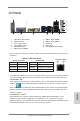
Motherboard Layout 2 3 1 6 5 4 18.3cm (7.2 in) PS2 Mouse PS2 Keyboard CHA_FAN2 CPU_FAN1 Top: Line In Center: Front Bottom: Mic In USB3_2_3 USB 2.0 T: USB2 B: USB3 RJ-45 LAN 8 10 A75iCafe RoHS 7 9 PCIE1 33 30.5cm (12.0 in) DDR3_B1 (64 bit, 240-pin module) USB 2.0 T: USB4 B: USB5 Dual Graphics USB 3.
I/O Panel 2 1 3 4 5 11 1 * 2 3 ** 4 5 6 10 9 PS/2 Mouse Port (Green) LAN RJ-45 Port Line In (Light Blue) Front Speaker (Lime) Microphone (Pink) USB 2.0 Ports (USB23) 8 7 8 9 10 11 7 6 USB 2.0 Ports (USB45) USB 3.0 Ports (USB01) DVI-D Port D-Sub Port PS/2 Keyboard Port (Purple) * There are two LED next to the LAN port. Please refer to the table below for the LAN port LED indications.
1. Introduction Thank you for purchasing ASRock A75iCafe motherboard, a reliable motherboard produced under ASRock’s consistently stringent quality control. It delivers excellent performance with robust design conforming to ASRock’s commitment to quality and endurance. This Quick Installation Guide contains introduction of the motherboard and step-bystep installation guide. More detailed information of the motherboard can be found in the user manual presented in the Support CD.
Platform Graphics Audio LAN - ATX Form Factor: 12.0-in x 7.2-in, 30.5 cm x 18.3 cm - All Solid Capacitor design - Support for Socket FM1 100W processors - 4 + 1 Power Phase Design - Supports AMD’s Cool ‘n’ QuietTM Technology - UMI-Link GEN2 - AMD A75 FCH (Hudson-D3) - Dual Channel DDR3 Memory Technology (see CAUTION 1) - 2 x DDR3 DIMM slots - Support DDR3 2400+(OC)/2133(OC)/1866/1600/1333/1066/ 800 non-ECC, un-buffered memory (see CAUTION 2) - Max.
English 6 Rear Panel I/O - Supports PXE I/O Panel SATA3 USB 3.0 Connector BIOS Feature Support CD Unique Feature - 1 x PS/2 Mouse Port - 1 x PS/2 Keyboard Port - 1 x D-Sub Port - 1 x DVI-D Port - 4 x Ready-to-Use USB 2.0 Ports - 2 x Ready-to-Use USB 3.0 Ports - 1 x RJ-45 LAN Port with LED (ACT/LINK LED and SPEED LED) - HD Audio Jack: Line in/Front Speaker/Microphone - 6 x SATA3 6.
- ASRock APP Charger (see CAUTION 7) - ASRock XFast USB (see CAUTION 8) Hardware Monitor OS Certifications - ASRock XFast LAN (see CAUTION 9) - ASRock XFast RAM (see CAUTION 10) - Hybrid Booster: - ASRock U-COP (see CAUTION 11) - CPU Temperature Sensing - Chassis Temperature Sensing - CPU/Chassis Fan Tachometer - CPU Quiet Fan - CPU/Chassis Fan Multi-Speed Control - Voltage Monitoring: +12V, +5V, +3.
CAUTION! English 1. This motherboard supports Dual Channel Memory Technology. Before you implement Dual Channel Memory Technology, make sure to read the installation guide of memory modules on page 13 for proper installation. 2. Whether 2400/2133/1866/1600MHz memory speed is supported depends on the CPU you adopt. If you want to adopt DDR3 2400/2133/1866/1600 memory module on this motherboard, please refer to the memory support list on our website for the compatible memory modules.
English 7. If you desire a faster, less restricted way of charging your Apple devices, such as iPhone/iPod/iPad Touch, ASRock has prepared a wonderful solution for you - ASRock APP Charger. Simply installing the APP Charger driver, it makes your iPhone charged much quickly from your computer and up to 40% faster than before.
13. EuP, stands for Energy Using Product, was a provision regulated by European Union to define the power consumption for the completed system. According to EuP, the total AC power of the completed system shall be under 1.00W in off mode condition. To meet EuP standard, an EuP ready motherboard and an EuP ready power supply are required. According to Intel’s suggestion, the EuP ready power supply must meet the standard of 5v standby power efficiency is higher than 50% under 100 mA current consumption.
2. Installation This is an ATX form factor (12.0-in x 7.2-in, 30.5 cm x 18.3 cm) motherboard. Before you install the motherboard, study the configuration of your chassis to ensure that the motherboard fits into it. Pre-installation Precautions Take note of the following precautions before you install motherboard components or change any motherboard settings. Before you install or remove any component, ensure that the power is switched off or the power cord is detached from the power supply.
2.1 CPU Installation o Step 1. Unlock the socket by lifting the lever up to a 90 angle. Step 2. Position the CPU directly above the socket such that the CPU corner with the golden triangle matches the socket corner with a small triangle. Step 3. Carefully insert the CPU into the socket until it fits in place. The CPU fits only in one correct orientation. DO NOT force the CPU into the socket to avoid bending of the pins. Step 4.
2.3 Installation of Memory Modules (DIMM) This motherboard provides two 240-pin DDR3 (Double Data Rate 3) DIMM slots, and supports Dual Channel Memory Technology. For dual channel configuration, you always need to install two identical (the same brand, speed, size and chiptype) memory modules in the DDR3 DIMM slots to activate Dual Channel Memory Technology. Otherwise, it will operate at single channel mode. 1. 2.
2.4 Expansion Slots (PCI and PCI Express Slots) There are 2 PCI slots and 5 PCI Express slots on this motherboard. PCI Slots: PCI slots are used to install expansion cards that have the 32-bit PCI interface. PCIE Slots: PCIE1 / PCIE3 / PCIE4 (PCIE x1 slot) is used for PCI Express cards with x1 lane width cards, such as Gigabit LAN card and SATA2 card.
2.5 CrossFireXTM and Quad CrossFireXTM Operation Guide This motherboard supports CrossFireX TM and Quad CrossFireX TM feature. CrossFireX TM technology offers the most advantageous means available of combining multiple high performance Graphics Processing Units (GPU) in a single PC. Combining a range of different operating modes with intelligent software design and an innovative interconnect mechanism, CrossFireXTM enables the highest possible level of performance and image quality in any 3D application.
Step 2. Connect two Radeon graphics cards by installing CrossFire Bridge on CrossFire Bridge Interconnects on the top of Radeon graphics cards. (CrossFire Bridge is provided with the graphics card you purchase, not bundled with this motherboard. Please refer to your graphics card vendor for details.) CrossFire Bridge or Step 3. Connect the DVI monitor cable to the DVI connector on the Radeon graphics card on PCIE2 slot.
2.5.2 Driver Installation and Setup Step 1. Power on your computer and boot into OS. Step 2. Remove the AMD driver if you have any VGA driver installed in your system. The Catalyst Uninstaller is an optional download. We recommend using this utility to uninstall any previously installed Catalyst drivers prior to installation. Please check AMD website for AMD driver updates. Step 3. Install the required drivers to your system. For Windows® XP OS: A.
Although you have selected the option “Enable CrossFireTM”, the CrossFireXTM function may not work actually. Your computer will automatically reboot. After restarting your computer, please confirm whether the option “Enable CrossFireTM” in “ATI Catalyst Control Center” is selected or not; if not, please select it again, and then you are able to enjoy the benefit of CrossFireXTM feature. Step 7. You can freely enjoy the benefit of CrossFireXTM or Quad CrossFireXTM feature.
2.6 AMD Dual Graphics Operation Guide This motherboard supports AMD Dual Graphics feature. AMD Dual Graphics brings multi-GPU performance capabilities by enabling an AMD A75 FCH (Hudson-D3) integrated graphics processor and a discrete graphics processor to operate simultaneously with combined output to a single display for blisteringly-fast frame rates. Currently, AMD Dual Graphics Technology is only supported with Windows® 7 OS, and is not available with Windows® VistaTM / XP OS.
Step 7. You can also click “AMD VISION Engine Control Center” on your Windows® taskbar to enter AMD VISION Engine Control Center. AMD VISION Engine Control Center Step 8. In AMD VISION Engine Control Center, please choose “Performance”. Click “AMD CrossFireTM”. Step 9. Click “Enable CrossFireTM” and click “Apply“ to save your change. Step 10. Reboot your system. Then you can freely enjoy the benefit of Dual Graphics feature.
2.7 Dual Monitor and Surround Display Features Dual Monitor Feature This motherboard supports dual monitor feature. With the internal VGA output support (D-Sub and DVI-D), you can easily enjoy the benefits of dual monitor feature without installing any add-on VGA card to this motherboard. This motherboard also provides independent display controllers for D-Sub and DVI-D to support dual VGA output so that D-sub and DVI-D can drive same or different display contents.
Surround Display Feature This motherboard supports surround display upgrade. With the internal VGA output support (D-Sub and DVI-D) and external add-on PCI Express VGA cards, you can easily enjoy the benefits of surround display feature. Please refer to the following steps to set up a surround display environment: 1. Install the PCI Express VGA cards on PCIE2 and PCIE5 slots. Please refer to page 14 for proper expansion card installation procedures for details. 2.
For Windows® 7 / 7 64-bit / VistaTM / VistaTM 64-bit OS: Right click the desktop, choose “Personalize”, and select the “Display HDCP Function HDCP function is supported on this motherboard. To use HDCP function with this motherboard, you need to adopt the monitor that supports HDCP function as well. Therefore, you can enjoy the superior display quality with high-definition HDCP encryption contents. Please refer to below instruction for more details about HDCP function.
2.8 ASRock Smart Remote Installation Guide ASRock Smart Remote is only used for ASRock motherboard with CIR header. Please refer to below procedures for the quick installation and usage of ASRock Smart Remote. Step1. Find the CIR header located next to the USB 2.0 header on ASRock motherboard. USB 2.0 header (9-pin, black) CIR header (4-pin, gray) Step2. Connect the front USB cable to the USB 2.0 header (as below, pin 1-5) and the CIR header.
3 CIR sensors in different angles 1. 2. 3. Only one of the front USB port can support CIR function. When the CIR function is enabled, the other port will remain USB function. Multi-Angle CIR Receiver is used for front USB only. Please do not use the rear USB bracket to connect it on the rear panel. Multi-Angle CIR Receiver can receive the multi-direction infrared signals (top, down and front), which is compatible with most of the chassis on the market.
2.9 Jumpers Setup The illustration shows how jumpers are setup. When the jumper cap is placed on pins, the jumper is “Short”. If no jumper cap is placed on pins, the jumper is “Open”. The illustration shows a 3-pin jumper whose pin1 and pin2 are “Short” when jumper cap is placed on these 2 pins. Jumper Setting Clear CMOS Jumper Description (CLRCMOS1) (see p.2, No. 14) Default Clear CMOS Note: CLRCMOS1 allows you to clear the data in CMOS.
2.10 Onboard Headers and Connectors Onboard headers and connectors are NOT jumpers. Do NOT place jumper caps over these headers and connectors. Placing jumper caps over the headers and connectors will cause permanent damage of the motherboard! Serial ATA2 Connectors (SATA_1: see p.2, No. 9) SATA_1 (SATA_2: see p.2, No. 10) (SATA_3: see p.2, No. 17) (SATA_4: see p.2, No. 18) (SATA_5: see p.2, No. 21) (SATA_6: see p.2, No.
USB 3.0 Header (19-pin USB3_2_3) IntA_P2_D+ IntA_P2_DGND IntA_P2_SSTX+ IntA_P2_SSTXGND IntA_P2_SSRX+ IntA_P2_SSRXVbus (see p.2 No. 8) 1 ID Besides two default USB 3.0 ports on the I/O panel, there is one USB 3.0 header on this motherboard. This USB 3.0 header can support two USB 3.0 ports. Vbus IntA_P1_SSRXIntA_P1_SSRX+ GND IntA_P1_SSTXIntA_P1_SSTX+ GND IntA_P1_DIntA_P1_D+ Infrared Module Header (5-pin IR1) (see p.2 No.
System Panel Header (9-pin PANEL1) This header accommodates several system front panel (see p.2 No. 16) functions. Connect the power switch, reset switch and system status indicator on the chassis to this header according to the pin assignments below. Note the positive and negative pins before connecting the cables. PWRBTN (Power Switch): Connect to the power switch on the chassis front panel. You may configure the way to turn off your system using the power switch.
Chassis Fan Connectors (4-pin CHA_FAN1) (see p.2 No. 13) GND +12V CHA_FAN_SPEED FAN_SPEED_CONTROL Please connect the fan cables to the fan connectors and match the black wire to the ground pin. (4-pin CHA_FAN2) (see p.2 No. 5) CPU Fan Connectors FAN_SPEED_CONTROL CPU_FAN_SPEED (4-pin CPU_FAN1) +12V (see p.2 No. 4) GND 1 2 3 4 Please connect the CPU fan cable to the connector and match the black wire to the ground pin.
Serial port Header (9-pin COM1) This COM1 header supports a serial port module. (see p.2 No.25) HDMI_SPDIF Header (2-pin HDMI_SPDIF1) (see p.2 No. 26) HDMI_SPDIF header, providing SPDIF audio output to HDMI VGA card, allows the system to connect HDMI Digital TV/ projector/LCD devices. Please connect the HDMI_SPDIF connector of HDMI VGA card to this header. 2.
2.13.1 Installing Windows® XP / XP 64-bit Without RAID Functions If you want to install Windows® XP / XP 64-bit on your SATA3 HDDs without RAID functions, please follow below steps. Using SATA3 HDDs without NCQ and Hot Plug functions (IDE mode) STEP 1: Set up UEFI. A. Enter UEFI SETUP UTILITY Advanced screen Storage Configuration. B. Set the “SATA Mode” option to [IDE]. STEP 2: Install Windows® XP / XP 64-bit OS on your system. 2.13.
3. BIOS Information The Flash Memory on the motherboard stores BIOS Setup Utility. When you start up the computer, please press or during the Power-On-Self-Test (POST) to enter BIOS Setup utility; otherwise, POST continues with its test routines. If you wish to enter BIOS Setup after POST, please restart the system by pressing + + , or pressing the reset button on the system chassis. The BIOS Setup program is designed to be user-friendly.
1. 主板簡介 謝謝你采用了華擎 A75iCafe 主板 , 本主板由華擎嚴格制造 , 質量可靠 , 穩定性好 , 能夠獲得卓越的性能。本安裝指南介紹了安裝主板的步驟。更加詳細的主板信息可參 看驅動光盤的用戶手冊。 由于主板規格和 BIOS 軟件將不斷升級 , 本手冊之相關內容變更恕不另 行通知。請留意華擎网站上公布的升級版本。你也可以在華擎網站找 到最新的顯卡和 CPU 支持表。 華擎网址:http://www.asrock.com 如果您需要與此主板有關的技術支持 , 請參觀我們的網站以了解您使用機 種的規格信息。 www.asrock.com/support/index.asp 1.1 包裝盒內物品 華擎 A75iCafe 主板 (ATX 規格 : 12.0 英吋 X 7.2 英吋 , 30.5 厘米 X 18.3 厘米 ) 華擎 A75iCafe 快速安裝指南 華擎 A75iCafe 支持光盤 兩條 Serial ATA(SATA) 數據線 ( 選配 ) 一塊 I/O 擋板 ASRock提醒您 ...
1.2 主板規格 處理器 芯片組 系統內存 擴展插槽 板載顯卡 音效 板載 LAN 功能 - ATX 規格 : 12.0 英吋 X 7.2 英吋 , 30.5 厘米 X 18.3 厘米 全固態電容設計 FM1 插槽支持 100W 處理器 4 + 1 電源相位設計 ™ 支持 AMD Cool ‘n’ Quiet 冷靜技術 UMI-Link GEN2 AMD A75 FCH (Hudson-D3) 支持雙通道 DDR3 內存技術(見警告 1) 配備 2 個 DDR3 DIMM 插槽 支持 DDR3 2400+( 超頻 )/2133( 超頻 )/1866/1600/1333/1066 /800 non-ECC、un-buffered 內存(見警告 2) 最高支持 16GB 系統容量(見警告 3) 2 x PCI Express 2.0 x16 插槽 (PCIE2 @ x16 模式 ; PCIE5 @ x4 模式 ) 3 x PCI Express 2.
Rear Panel I/O ( 后面板輸入 / 輸出接口 ) SATA3 USB 3.0 連接頭 BIOS 支持光盤 簡體中文 獨家功能 36 I/O 界面 - 1 個 PS/2 鼠標接口 - 1 個 PS/2 鍵盤接口 - 1 個 D-Sub 接口 - 1 個 DVI-D 接口 - 4 個可直接使用的 USB 2.0 接口 - 2 個可直接使用的 USB 3.0 接口 - 1 個 RJ-45 局域网接口與 LED 指示燈 (ACT/LINK LED 和 SPEED LED) - 高保真音頻插孔:音頻輸入 / 前置喇叭 / 麥克風 - 6 x SATA3 6.0Gb/s 連接頭 , 支持 RAID (RAID 0, RAID 1 和 RAID 10), NCQ, AHCI 和熱插拔功能 - 2 x 后置 USB 3.0 連接頭,支持 USB 1.0/2.0/3.0 到 5Gb/s - 1 x 前置 USB 3.0 連接頭 ( 支持 2 個 USB 3.
- 華擎 XFast USB(見警告 8) - 華擎 XFast LAN(見警告 9) - 華擎 XFast RAM(見警告 10) - Hybrid Booster( 安心超頻技術 ): - ASRock U-COP(見警告 11) 硬件監控器 - CPU 溫度偵測 - 主板溫度偵測 - CPU/ 機箱風扇轉速計 - CPU 靜音風扇 - CPU/ 機箱風扇多速控制 - 電壓範圍:+12V, +5V, +3.3V, 核心電壓 ® ® 操作系統 - Microsoft Windows 7/7 64 位元 /VistaTM/VistaTM 64 位元 / XP SP3/XP 64 位元适用于此主板(見警告 12) 認證 - FCC, CE, WHQL - 支持 ErP/EuP( 需要同時使用支持 ErP/EuP 的電源供應器 ) (見警告 13) * 請參閱華擎網站了解詳細的產品信息 : http://www.asrock.
警告! 簡體中文 1、 這款主板支援雙通道內存技術。在您實現雙通道內存技術之前,為能正確 安裝,請確認您已經閱讀了第 13 頁的內存模組安裝指南。 2、 2400/2133/1866/1600MHz 內存頻率是否支持在于您使用的 CPU。如果您想 在這款主板上使用 D D R3 2400/2133/1866/1600 內存條 , 請查閱我們網站 的內存支持列表了解兼容的內存。華擎網站 : http://www.asrock.
簡體中文 10、華擎 XFast RAM 是 ASRock Extreme Tuning Utility (AXTU) 中加入的一 ® 項新功能。它能充分利用 Windows 操作系統 32-bit CPU 無法使用的內存 空間。華擎 XFast RAM 可縮短之前訪問過的网站的加載時間,從而加快网 絡衝浪速度。此外,它還能提升 Adobe Photoshop 運行的速度高達五倍之 多。華擎 XFast RAM 的另一項优勢是它能減少訪問 SSD 或 HDD 的頻次,從 而延長它門的使用壽命。 11、 當檢測到 CPU 過熱問題時,系統會自動關機。在您重新啟動系統之前,請 檢查主板上的 C P U 風扇是否正常運轉並拔出電源線,然后再將它插回。為 了提高散熱性,在安裝 PC 系統時請在 CPU 和散熱器之間涂一層導熱膠。 ® ® 12、 Microsoft Windows XP / XP 64-bit 系統不支持華擎 XFast RAM。 13、 EuP, 全稱 Energy Using Product( 能耗產品 ), 是歐盟用來定義完整系統 耗電量的規定。根據 E u P 的規定 , 一個完整系統在關機
1.
1.4 板載接頭和接口 板載接頭和接口不是跳線。切勿將跳線帽放置在這些接頭和接口上。將 跳線帽放置在接頭和接口上將會導致主板的永久性損壞! Serial ATA2 接口 (SATA_1: 見第 2 頁第 9 項 ) SATA_1 SATA_2 (SATA_2: 見第 2 頁第 10 項 ) (SATA_3: 見第 2 頁第 17 項 ) (SATA_4: 見第 2 頁第 18 項 ) (SATA_5: 見第 2 頁第 21 項 ) SATA_3 SATA_4 SATA_5 SATA_6 這裡有六組 Serial ATA3 (SATA3) 接口支持 Serial (SATA) 數據線作為內部儲存 設置。目前 SATA3 界面理論 上可提供高達 6.0Gb/s 的數 據傳輸速率。 (SATA_6: 見第 2 頁第 20 項 ) Serial ATA (SATA) 數據線 ( 選配 ) SATA 數據線的任意一端均可 連接 SATA3 硬盤或者主板上的 SATA3 接口。 USB 2.
紅外線模塊接頭 (5 針 IR1) ( 見第 2 頁第 24 項 ) IRTX +5VSB DUMMY 這個接頭支持一個選配的無 線發送和接受紅外線的 模塊。 1 GND IRRX 前置音頻面板接頭 GND PRESENCE# MIC_RET OUT_RET (9 針 HD_AUDIO1) ( 見第 2 頁第 27 項 ) 可以方便連接音頻設備。 1 OUT2_L J_SENSE OUT2_R MIC2_R MIC2_L 1. 高保真音頻 (High Definition Audio, HDA) 支持智能音頻接口檢測功能 (Jack Sensing), 但是機箱面板的連線必須支持 HDA 才能正常使用。請按我 們提供的手冊和機箱手冊上的使用說明安裝您的系統。 2. 如果您使用 AC’97 音頻面板 , 請按照下面的步驟將它安裝到前面板音頻接針 : A. 將 Mic_IN(MIC) 連接到 MIC2_L。 B. 將 Audio_R(RIN) 連接到 OUT2_R, 將 Audio_L(LIN) 連接到 OUT2_L。 C.
根據下面的針腳說明連接機箱上的電源開關、重啟按鈕與系統狀態 指示燈到這個排針。根據之前請注意針腳的正負極。 PWRBTN( 電源開關 ): 連接機箱前面板的電源開關。您可以設置用電源鍵關閉系統的方式。 RESET( 重啟開關 ): 連接機箱前面板的重啟開關。當電腦死機且無法正常重新啟動時 , 可 按下重啟開關重新啟動電腦。 PLED( 系統電源指示燈 ): 連接機箱前面板的電源狀態指示燈。當系統運行時 , 此指示燈亮起。 當系統處于 S1 待機模式時 , 此指示燈保持閃爍。當系統處于 S3/S4 待 機模式或關機 (S5) 模式時 , 此指示燈熄滅。 HD LED( 硬盤活動指示燈 ): 連接機箱前面板的硬盤動作指示燈。當硬盤正在讀取或寫入數據時 , 此指示燈亮起。 前面板設計因機箱不同而有差異。前面板模塊一般由電源開關、 重啟開關、電源指示燈、硬盤動作指示燈、喇叭等構成。將您的機 箱前面板連接到此排針時 , 請確認連接線與針腳上的說明相對應。 機箱喇叭接頭 (4 針 SPEAKER1) 請將機箱喇
CPU 風扇接頭 (4 針 CPU_FAN1) FAN_SPEED_CONTROL CPU_FAN_SPEED +12V GND ( 見第 2 頁第 4 項 ) 請將 CPU 風扇連接線接到這個 接頭,並讓黑線與接地的針腳 相接。 1 2 3 4 雖然此主板支持 4-Pin CPU 風扇 (Quiet Fan, 靜音風扇 ), 但是沒有調速功能的 3-Pin CPU 風扇仍然可以在此主板上正常運行。如果您打算將 3-Pin CPU 風扇 連接到此主板的 CPU 風扇接口 , 請將它連接到 Pin 1-3。 Pin 1-3 連接 3-Pin 風扇的安裝 ATX 電源接頭 (24 針 ATXPWR1) 12 24 1 13 請將 ATX 電源供應器連接到這 個接頭。 ( 見第 2 頁第 7 項 ) 雖然此主板提供 24-pin ATX 電源接口 , 但是您仍然可以使用 傳統的 20-pin ATX 電源。為了使用 20-pin ATX 電源 , 請順著 Pin 1 和 Pin 13 插上電源接頭。 12 24 20-Pin ATX 電源安裝說明
( 見第 2 頁第 26 項 ) HDMI_SPDIF 接頭,提供 SPDIF 音頻輸出至 HDMI 顯卡,支持 將電腦連接至帶 HDMI 的數字 電視 / 投影儀 / 液晶顯示器等 設備。請將 HDMI 顯卡的 HDMI_SPDIF 接口連接到這個 接頭。 簡體中文 HDMI_SPDIF 接頭 (2 針 HDMI_SPDIF1) ASRock A75iCafe Motherboard 45
2. BIOS 信息 主板上的 Flash Memory 存儲了 BIOS 設置程序。請再啟動電腦進行開機自檢 (POST) 時按下 < F2> 或 < D e l > 鍵進入 B I O S 設置程序;此外,你也可以讓開機自檢 ( P O S T ) 進行常規檢驗。如果你需要在開機自檢 ( P O S T ) 之后進入 B I O S 設置程序,請按下 ++ 鍵重新啟動電腦,或者按下系統面板上的重啟按鈕。有關 BIOS 設置的詳細信息,請查閱隨機支持光盤裡的用戶手冊 (PDF 文件 )。 3. 支持光盤信息 ® ® 本主板支持各種微軟視窗操作系統:Microsoft Windows 7/7 64 位元 /Vista TM / VistaTM 64 位元 /XP SP3/XP 64 位元。主板隨機支持光盤包含各種有助于提高主板效 能的必要驅動和實用程序。請將隨機支持光盤放入光驅裡,如果電腦的“自動運行” 功能已啟用,屏幕將會自動顯示主菜單。如果主菜單不能自動顯示,請查找支持光盤 內 BIN 文件夾下的“ASSETUP.
電子信息產品污染控制標示 依據中國發布的「電子信息產品污染控制管理辦法」及 SJ/T 11364-2006「電子信息 產品污染控制標示要求」,電子信息產品應進行標示,藉以向消費者揭露產品中含有 的有毒有害物質或元素不致發生外洩或突變從而對環境造成污染或對人身、財產造成 嚴重損害的期限。依上述規定,您可于本產品之印刷電路板上看見圖一之標示。圖一 中之數字為產品之環保使用期限。由此可知此主板之環保使用期限為 10 年。 圖一 有毒有害物質或元素的名稱及含量說明 若您慾了解此產品的有毒有害物質或元素的名稱及含量說明,請參照以下表格及說 明。 有害物質或元素 部件名稱 鉛 (Pb) 鎘 (Cd) 汞 (Hg) 六价鉻 (Cr(VI)) 多溴聯苯 (PBB) 多溴二苯醚 (PBDE) 印刷電路板 X O O O O O 及電子組件 外部信號連 X O O O O O 接頭及線材 簡體中文 O: 表示該有毒有害物質在該部件所有均質材料中的含量均在 SJ/T 11363-2006 標準規定 的限量要求以下。 X: 表示該有毒有害物質至少在該部件的某一均質材料中的含量超出 SJ/T 11363-
Installing OS on a HDD Larger Than 2TB in AHCI Mode This motherboard is adopting UEFI BIOS that allows Windows® OS to be installed on a large size HDD (>2TB). Please follow below procedure to install the operating system. 1. Please make sure to use Windows® VistaTM 64-bit (with SP1 or above) or Windows® 7 64-bit. 2. Press or at system POST. Set AHCI Mode in UEFI Setup Utility > Advanced > Storage Configuration > SATA Mode. 3.
Installing OS on a HDD Larger Than 2TB in RAID Mode This motherboard is adopting UEFI BIOS that allows Windows® OS to be installed on a large size HDD (>2TB). Please follow below procedure to install the operating system. 1. Please make sure to use Windows® VistaTM 64-bit (with SP1 or above) or Windows® 7 64-bit. 2. Press or at system POST. Set RAID Mode in UEFI Setup Utility > Advanced > Storage Configuration > SATA Mode. 3. Choose onboard RAID 3TB+ unlocker > UEFI Mode For GPT partition.
7. And then key in drvcfg –s [Drv number] [Ctrl number] to enter Raid Utility. For example: key in drvcfg –s 4E B5. 8. Choose Logical Drive Main Menu to set up Raid Drive. 9. Choose Logical Drive Create Menu to create a Raid Drive. 10. Choose Usable Physical Drive List to select Raid HDD.
11. Press Space on keyboard to toggle checkbox. 12. Choose Ld Size setting, and key in the Raid size. 13. After set up Raid size, please click Start to Create. English 14. Press to exit Utility. 15. During reboot, please press to enter Boot Manual. Choose UEFI: SCSI CD/DVD Drive. * This option only shows on Windows® 7 64-bit and VistaTM 64-bit OS.
16. Follow Windows® Installation Guide to install OS. If you install Windows® 7 64-bit / VistaTM 64-bit in a large hard disk (ex. Disk volume > 2TB), it may take more time to boot into Windows® or install driver/ utilities. If you encounter this problem, you will need to following instructions to fix this problem. Windows® VistaTM 64-bit: Microsoft ® does not provide hotfix for this problem. Below steps are Microsoft® suggested solution: A. Disable System Restore. a.
B. Disable “Volume Shadow Copy” service. a. Type “computer management” in the Start Menu, then press “Enter”. b. Go to “Services and Applications>Services”; Then double click “Volume Shadow Copy”. English c. Set “Startup type” to “Disable” then Click “OK”.
C. Reboot your system. D. After reboot, please start to install motherboard drivers and utilities. Windows® 7 64-bit: A. Please request the hotfix KB2505454 thru this link: http://support.microsoft.com/kb/2505454/ B. After installing Windows® 7 64-bit, install the hotfix kb2505454. (This may take long time; >30 mins.) C. Reboot your system. (It may take about 5 mins to boot.) D. The Windows® will install this hotfix then reboot by itself. E. Please start to install motherboard drivers and utilities. 17.