AD2550RA/U3S3 AD2550R/U3S3 AD2550R User Manual Version 1.0 Published Feb 2013 Copyright©2013 ASRock INC. All rights reserved.
Copyright Notice: No part of this manual may be reproduced, transcribed, transmitted, or translated in any language, in any form or by any means, except duplication of documentation by the purchaser for backup purpose, without written consent of ASRock Inc. Products and corporate names appearing in this manual may or may not be registered trademarks or copyrights of their respective companies, and are used only for identification or explanation and to the owners’ benefit, without intent to infringe.
Contents 1 Introduction........................................................ 5 1.1 1.2 1.3 1.4 1.5 Package Contents................................................ Specifications....................................................... Motherboard Layout............................................. I/O Panel.............................................................. Block Diagram...................................................... 5 6 10 16 19 2 Installation.........................................
3 UEFI SETUP UTILITY.......................................... 33 3.1 Introduction.......................................................... 33 3.2 3.3 3.4 3.5 3.6 3.7 3.1.1 UEFI Menu Bar............................................ 3.1.2 Navigation Keys.......................................... Main Screen......................................................... Advanced Screen................................................. 3.3.1 CPU Configuration...................................... 3.3.
Chapter 1: Introduction Thank you for purchasing ASRock AD2550RA/U3S3 / AD2550R/U3S3 / AD2550R motherboard, a reliable motherboard produced under ASRock’s consistently stringent quality control. It delivers excellent performance with robust design conforming to ASRock’s commitment to quality and endurance. In this manual, chapter 1 and 2 contains the introduction of the motherboard and step-by-step hardware installation guide.
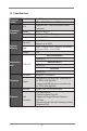
1.2 Specifications Physical Status Processor System System Memory Form Factor Mini ITX Dimension 6.7'' x 6.7'' (17.02 cm x17.02 cm) CPU Supports Intel® Dual-Core Atom D2550 Processor Socket micro-FCBGA11 Power Phase 1+1 Power Phase Design Chipset Intel® ICH10R Capacity 2 x SO-DIMM slots Support up to 4GB Type Single Channel DDR3 memory technology Supports DDR3 1066 DIMM Voltage 1.
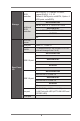
SATA controller Intel ICH10R : 5* x SATA2 3.0 Gb/s , support RAID 0, 1, 5, 10 (Default:5 SATA ports, w/eSATA ; Option: 6 SATA ports. wo/eSATA) AD2550RA/U3S3 Storage Marvell SE9172: 2 x SATA3 6.0 Gb/s Additional SATA controller AD2550R/U3S3 Marvell SE9172: 2 x SATA3 6.0 Gb/s AD2550R N/A PS/2 KB/ mouse 1 VGA port D-sub x 1 , HDMI x1 eSATA 1 (If without eSATA, the number of SATA2 ports will change from 5 to 6) AD2550RA/U3S3 6 USB 2.
Type A USB 2.0 port 1 AD2550RA/U3S3 2 (Each support 2 USB 2.0) USB 2.0 header AD2550R/U3S3 2 (Each support 2 USB 2.0) AD2550R 1 (Each support 2 USB 2.0) AD2550RA/U3S3 Etron EJ188: 1 x USB 3.0 header (Each support 2 USB 3.0) Internal Connector USB 3.0 header AD2550R/U3S3 Etron EJ188: 1 x USB 3.0 header (Each support 2 USB 3.
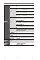
Hardware Monitor Temperature - CPU Temperature Sensing - System Temperature Sensing Fan - CPU/Rear/Front Fan Tachometer - CPU Quiet Fan (Allow Chassis Fan Speed Auto-Adjust by CPU Temperature) - CPU Fan Multi-Speed Control Voltage Voltage Monitoring: +12V, +5V, +3V, CPU Vcore, memory Support OS OS Features Unique Features Microsoft® Windows® 7 / Home Server 2011 / Storage Server 2008 R2 / Server 2008 R2 and Fedora ( 64bit OS* no g raphic driver support, need to use inbox graphic driver) - ASRock I
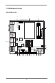
1.3 Motherboard Layout AD2550RA/U3S3 3 1 2 4 5 17.0cm (6.7 in) RoHS AD2550RA/U3S3 CPU_FAN1 HDMI1 USB 2.0 T: USB2 B: USB3 USB 2.0 T: USB4 B: USB5 Top: RJ-45 USB 2.0 T: USB6 B: USB7 Top: RJ-45 6 17.0cm (6.7 in) eSATA FSB800 FSB800 CPU_FAN2 DDR3_A2 (64 bit, 204-pin module) COM1 VGA1 DDR3_A1 (64 bit, 204-pin module) USB 3.
1 CPU Fan Connector (CPU_FAN1) 2 CPU Fan Connector (CPU_FAN2) 3 USB 3.0 Header (USB3_23, Black) 4 CPU Heatsink 5 2 x 204-pin DDR3 SO-DIMM Slots (DDR3_A1, DDR3_A2, Black) 6 ATX Power Connector (ATXPWR1) 7 Chassis Fan Connector (CHA_FAN1) 8 USB 2.
AD2550R/U3S3 3 1 2 4 5 17.0cm (6.7 in) RoHS AD2550R/U3S3 CPU_FAN1 HDMI1 USB 2.0 T: USB2 B: USB3 USB 2.0 T: USB4 B: USB5 Top: RJ-45 USB 2.0 T: USB6 B: USB7 Top: RJ-45 LAN 6 17.0cm (6.7 in) eSATA FSB800 FSB800 CPU_FAN2 DDR3_A2 (64 bit, 204-pin module) VGA1 COM1 DDR3_A1 (64 bit, 204-pin module) USB 3.
1 CPU Fan Connector (CPU_FAN1) 2 CPU Fan Connector (CPU_FAN2) 3 USB 3.0 Header (USB3_23, Black) 4 CPU Heatsink 5 2 x 204-pin DDR3 SO-DIMM Slots (DDR3_A1, DDR3_A2, Black) 6 ATX Power Connector (ATXPWR1) 7 Chassis Fan Connector (CHA_FAN1) 8 USB 2.
AD2550R 1 2 3 4 17.0cm (6.7 in) CPU_FAN1 HDMI1 USB 2.0 T: USB2 B: USB3 USB 2.0 T: USB4 B: USB5 Top: RJ-45 USB 2.0 T: USB6 B: USB7 Top: RJ-45 LAN 5 17.0cm (6.7 in) eSATA FSB800 FSB800 VGA1 COM1 CPU_FAN2 DDR3_A2 (64 bit, 204-pin module) AD2550R DDR3_A1 (64 bit, 204-pin module) USB 2.
1 CPU Fan Connector (CPU_FAN1) 2 CPU Fan Connector (CPU_FAN2) 3 CPU Heatsink 4 2 x 204-pin DDR3 SO-DIMM Slots (DDR3_A1, DDR3_A2, Black) 5 ATX Power Connector (ATXPWR1) 6 Chassis Fan Connector (CHA_FAN1) 7 SATA2 Connector (SATA2_2, Blue) 8 SATA2 Connector (SATA2_0, Blue) 9 SATA2 Connector (SATA2_1, Blue) 10 SATA2 Connector (SATA2_3, Blue) 11 SATA2 Connector (SATA2_4, Blue) 12 USB 2.0 Header (USB89, Blue) 13 System Panel Header (PANEL1, White) 14 PCI Express 1.
1.4 I/O Panel AD2550RA/U3S3 1 2 3 4 5 6 8 7 9 10 17 16 15 14 13 1 PS/2 Keyboard / Mouse Port (Green) 2 COM Port 3 USB 2.0 Ports (USB23) * 4 LAN RJ-45 Port * 5 LAN RJ-45 Port 6 Central / Bass (Orange) 7 Rear Speaker (Black) 8 Line In (Light Blue) 9 Front Speaker (Lime) 10 11 12 13 14 15 16 17 12 11 Microphone (Pink) Optical SPDIF Out Port USB 2.0 Ports (USB67) USB 2.0 Ports (USB45) eSATA Port HDMI Port VGA Port USB 3.0 Ports (USB01) * There are two LEDs on each LAN port.
AD2550R/U3S3 1 2 11 10 3 4 9 1 PS/2 Keyboard / Mouse Port (Green) 2 COM Port 3 USB 2.0 Ports (USB23) * 4 LAN RJ-45 Port * 5 LAN RJ-45 Port 5 8 7 6 7 8 9 10 11 USB 2.0 Ports (USB67) USB 2.0 Ports (USB45) eSATA Port HDMI Port VGA Port USB 3.0 Ports (USB01) 6 * There are two LEDs on each LAN port. Please refer to the table below for the LAN port LED indications.
AD2550R 1 2 11 10 3 4 9 1 PS/2 Keyboard / Mouse Port (Green) 2 COM Port 3 USB 2.0 Ports (USB01) * 4 LAN RJ-45 Port * 5 LAN RJ-45 Port 5 8 7 6 7 8 9 10 11 USB 2.0 Ports (USB67) USB 2.0 Ports (USB54) eSATA Port HDMI Port VGA Port USB 2.0 Ports (USB01) 6 * There are two LEDs on each LAN port. Please refer to the table below for the LAN port LED indications.
1.5 Block Diagram AD2550RA/U3S3 INTEL Atom D2550 Processor VGA CONN Diboofm!B PLTRST# RSTOUT0# Etron EJ188 USB 3.
AD2550R/U3S3 INTEL Atom D2550 Processor VGA CONN Diboofm!B PLTRST# ENJ!y5 RSTOUT2# QDJf!y2!Cvt Etron EJ188 USB 3.
AD2550R INTEL Atom D2550 Processor VGA CONN Diboofm!B PLTRST# ENJ!y5 RSTOUT0# QDJf!y2!Cvt RSTOUT0# QDJf!y2!Cvt QDJf!y2!Cvt INTEL ICH10R TBUB TQJ PLTRST# PCIE Slot x4 Super I/O NUVOTON NTC6776D 20 1066 MHz HDMI CONN EEJ1 RSTOUT2# DDR3 x2 VTC!3/1 RS232 x1 PS2 KB/MS H/W Monitor Intel 82574L GLAN1 Intel 82574L GLAN1 SATAII x5 eSATA x1 AMI SPI 16M ROM High-Speed USB Rear x6 port Front x4 port 1 port on MiniPCIE 1 port on Type A
Chapter 2: Installation This is a Mini-ITX form factor (6.7" x 6.7", 17.0 x 17.0 cm) motherboard. Before you install the motherboard, study the configuration of your chassis to ensure that the motherboard fits into it. Make sure to unplug the power cord before installing or removing the motherboard. Failure to do so may cause physical injuries to you and damages to motherboard components. 2.1 Screw Holes Place screws into the holes indicated by circles to secure the motherboard to the chassis.
2.3 Installation of Memory Modules (SO-DIMM) AD2550RA/U3S3 / AD2550R/U3S3 / AD2550R motherboard provides two 204-pin DDR3 (Double Data Rate 3) SO-DIMM slots. 1. It is not allowed to install a DDR or DDR2 memory module into DDR3 slot; otherwise, this motherboard and SO-DIMM may be damaged. 2. Please install the memory module from DDR3_A2 slot for the first priority. Installing a SO-DIMM Please make sure to disconnect power supply before adding or removing SO-DIMMs or the system components. Step 1.
2.4 Expansion Slots (PCI Express Slots) There is 1 PCI Express slot on this motherboard. PCIE slots: AD2550RA/U3S3 / AD2550R/U3S3 PCIE1 (PCIE 1.0 x1 slot) is used for PCI Express x1 lane width cards. AD2550R PCIE1 (PCIE 1.0 x4 slot) is used for PCI Express x4 lane width cards. Installing an expansion card Step 1. Step 2. Step 3. Step 4. Step 5. Step 6. Before installing an expansion card, please make sure that the power supply is switched off or the power cord is unplugged.
2.5 Onboard Headers and Connectors Onboard headers and connectors are NOT jumpers. Do NOT place jumper caps over these headers and connectors. Placing jumper caps over the headers and connectors will cause permanent damage to the motherboard! SATA2_4 SATA2_2 SATA2_3 Serial ATA3 Connectors SATA3_0 SATA3_1 (see p.10,12) Serial ATA (SATA) Data Cable SATA2_0 (see p.10,12,14) SATA2_1 Serial ATA2 Connectors These five Serial ATA2 (SATA2) connectors support SATA data cables for internal storage devices.
USB 2.0 Headers and Ports Besides two default USB 2.0 ports on the I/O panel, (9-pin USB0_1) (see p.10,12) there are are two USB 2.0 headers and one port on this motherboard. Each USB 2.0 header can support two USB 2.0 ports. (9-pin USB8_9) (see p.10,12,14) (USB6) (see p.10,12,14) TPMS Header This connector supports Trusted Platform Module (TPM) system, which can securely store keys, digital certificates, passwords, and data.
PWRBTN (Power Switch): Connect to the power switch on the chassis front panel. You may configure the way to turn off your system using the power switch. RESET (Reset Switch): Connect to the reset switch on the chassis front panel. Press the reset switch to restart the computer if the computer freezes and fails to perform a normal restart. PLED (System Power LED): Connect to the power status indicator on the chassis front panel. The LED is on when the system is operating.
B. Internet status indicator (2-pin LAN1_LED, LAN2_LED) These two 2-pin headers allow you to use the Gigabit internet indicator cable to connect to the LAN status indicator. When this indicator flickers, it means that the internet is properly connected. C. Chassis intrusion pin (4-pin CHASSIS) This header is provided for host computer chassis with chassis intrusion detection designs.
CPU Fan Connectors (4-pin CPU_FAN1) (see p.10,12,14) GND +12V CPU_FAN_SPEED FAN_SPEED_CONTROL Please connect the CPU fan cable to the connector and match the black wire to the ground pin. Though this motherboard provides a 4-Pin CPU fan (Quiet Fan) connector, 3-Pin CPU fans can still work successfully even without the fan speed control function. If you plan to connect a 3-Pin CPU fan to the CPU fan connector on this motherboard, please connect it to Pin 1-3.
Chassis Fan Connector (3-pin CHA_FAN1) GND +12V CHA_FAN_SPEED (see p.10,12,14) match the black wire to the ground pin. USB 3.0 Headers (see p.10,12) Please connect the fan cable to the fan connector and IntA_P_D+ IntA_P_DGND IntA_P_SSTX+ IntA_P_SSTXGND IntA_P_SSRX+ IntA_P_SSRXVbus ID 1 Vbus IntA_P_SSRXIntA_P_SSRX+ GND IntA_P_SSTXIntA_P_SSTX+ GND IntA_P_DIntA_P_D+ 29 Besides eight default USB 3.0 ports on the I/O panel, there are two USB 3.0 header on this motherboard. Each USB 3.
2.6 Driver Installation Guide To install the drivers to your system, please insert the support CD to your optical drive first. Then, the drivers compatible to your system can be autodetected and listed on the support CD driver page. Please follow the order from top to bottom to install those required drivers. Therefore, the drivers you install can work properly.
2.7 Hot Plug for Hard Disk Drives This motherboard supports Hot Plug for HDDs in AHCI / RAID mode. What is Hot Plug? If the HDDs are NOT set for RAID, it is called “Hot Plug” for the action to insert and remove the HDDs while the system is still powered on and in working condition. However, please note that it cannot perform Hot Plug if the OS has been installed into the HDD.
Chapter 3: UEFI SETUP UTILITY 3.1 Introduction This section explains how to use the UEFI SETUP UTILITY to configure your system. The UEFI chip on the motherboard stores the UEFI SETUP UTILITY. You may run the UEFI SETUP UTILITY when you start up the computer. Please press or during the Power-On-Self-Test (POST) to enter the UEFI SETUP UTILITY, otherawise, POST will continue with its test routines.
3.1.2 Navigation Keys Use < > key or < > key to choose among the selections on the menu bar, and use < > key or < > key to move the cursor up or down to select items, then press to get into the sub screen. You can also use the mouse to click your required item. Please check the following table for the descriptions of each navigation key.
3.2 Main Screen When you enter the UEFI SETUP UTILITY, the Main screen will appear and display the system overview.
3.3 Advanced Screen In this section, you may set the configurations for the following items: CPU Configuration, Chipset Configuration, Storage Configuration, Super IO Configuration, ACPI Configuration, USB Configuration, Voltage Control, ,Trusted Computing, and Serial Port Console Redirection. Setting wrong values in this section may cause the system to malfunction. Instant Flash Instant Flash is a UEFI flash utility embedded in Flash ROM.
3.3.1 CPU Configuration Intel Hyper Threading Technology To enable this feature, a computer system with an Intel processor that supports Hyper-Threading technology and an operating system that includes optimization for this technology is required. This option will be hidden if the installed CPU does not support HyperThreading technology. No-Execute Memory Protection No-Execution (NX) Memory Protection Technology is an enhancement to the IA-32 Intel Architecture.
3.3.2 Chipset Configuration Spread Spectrum for Clockgen Select [Disabled] for better system stability. Restore on AC/Power Loss This allows you to set the power state after an unexpected AC/ power loss. If [Power Off] is selected, the AC/power remains off when the power recovers. If [Power On] is selected, the AC/power resumes and the system starts to boot up when the power recovers. Onboard LAN1 This allows you to enable or disable the Onboard LAN1.
3.3.3 Storage Configuration Onboard SATAII Mode This item is for eSATA 5 and SATA2_0 to SATA2_4 ports. Use this to select SATA mode. Configuration options: [IDE Mode], [AHCI Mode], [RAID Mode] and [Disabled]. The default value is [AHCI Mode]. AHCI (Advanced Host Controller Interface) supports NCQ and other new features that will improve SATA disk performance but IDE mode does not have these advantages. Hard Disk S.M.A.R.T. Use this to enable or disable S.M.A.R.T.
We recommend to use Intel® ICH10R SATA ports (SATA2_0 to SATA2_4) for your bootable devices. This will minimum your boot time and get the best performance. But if you still want to boot from the Marvell SATA3 controller, you can enable it from the UEFI.
3.3.4 Super IO Configuration COM1 Port Use this item to enable or disable the COM1 port. COM1 Port Address Use this to set the address for the onboard serial port. Configuration options: [3F8h / IRQ4] and [3E8h / IRQ4]. WDT Timeout Reset This allows you to enable or disable the Watchdog Timeout Reset function. The default value is [Disabled].
3.3.5 ACPI Configuration Suspend to RAM Use this item to select whether to auto-detect or disable the Suspend-to-RAM feature. Selecting [Auto] will enable this feature if the OS supports it. Check Ready Bit Use this to enable or disable Check Ready Bit. ACPI HPET Table Use this item to enable or disable ACPI HPET Table. The default value is [Enabled]. Deep S5 Use this item to enable or disable the Deep S5 (Shut Down) power saving mode.
RTC Alarm Power On Use this item to enable or disable RTC (Real Time Clock) to power on the system. USB Keyboard/Remote Power On Use this item to enable or disable USB Keyboard/Remote to turn on the system from the power-soft-off mode. USB Mouse Power On Use this item to enable or disable USB Mouse to turn on the system from the power-soft-off mode.
3.3.6 USB Configuration USB 2.0 Controller Use this item to enable or disable the use of USB 2.0 controller. USB 3.0 Controller Use this item to enable or disable the use of USB 3.0 controller. Legacy USB Support Use this option to select legacy support for USB devices. There are four configuration options: [Enabled], [Auto], [Disabled] and [UEFI Setup Only]. The default value is [Enabled]. Please refer to below descriptions for the details of these four options: [Enabled] - Enables support for legacy USB.
3.3.7 Voltage Control . DRAM Voltage Use this to select DRAM Voltage. The default value is [Auto]. +1.05V_CORE Voltage Use this to select +1.05V_CORE Voltage. The default value is [Auto]. +1.5V_ICH Voltage Use this to select +1.5V_ICH Voltage. The default value is [Auto]. +1.1V_ICH Voltage Use this to select +1.1V_ICH Voltage. The default value is [Auto].
3.3.8 Trusted Computing TPM Support Use this option to enable or disable BIOS support for security devices. The default value is [Disabled].
3.3.9 Serial Port Console Redirection Console Redirection Use this option to enable or disable Console Redirection. Console Redirection Settings Use this option to configure Console Redirection Settings.
3.4 Hardware Health Event Monitoring Screen In this section, it allows you to monitor the status of the hardware on your system, including the parameters of the CPU temperature, motherboard temperature and the critical voltage. CPU Fan 1 Setting This allows you to set the speed of CPU fan 1. The default value is [Full On]. CPU Fan 2 Setting This allows you to set the speed of CPU fan 2. The default value is [Full On]. Case Open Feature This allows you to enable or disable the Case Open Feature.
3.5 Boot Screen In this section, it will display the available devices on your system for you to configure the boot settings and the boot priority. Boot Option #1 Select boot option #1. Boot Option #2 Select boot option #2. USB Device BBS Priorities Set the boot priorities for USB devices. Setup Prompt Timeout This shows the number of seconds to wait for setup activation key. 65535(0XFFFF) means indefinite waiting.
Boot From Onboard LAN Use this item to enable or disable the Boot From Onboard LAN feature.
3.6 Security Screen In this section, you may set or change the supervisor/user password for the system. For the user password, you may also clear it. Secure Boot Use this to enable or disable Secure Boot Control. The default value is [Disabled].
3.7 Exit Screen Save Changes and Exit When you select this option, the following message “Save configuration changes and exit setup?” will pop-out. Select [Yes] to save the changes and exit the UEFI SETUP UTILITY. Discard Changes and Exit When you select this option, the following message “Discard changes and exit setup?” will pop-out. Select [Yes] to exit the UEFI SETUP UTILITY without saving any changes. Discard Changes When you select this option, the following message “Discard changes?” will pop-out.
Chapter 4: Software Support 4.1 Install Operating System This motherboard supports Microsoft® Windows® Server 2003 / 2003 R2 / 2008 / 2008 R2 / Linux compliant. Because motherboard settings and hardware options vary, use the setup procedures in this chapter for general reference only. Refer your OS documentation for more information. 4.2 Support CD Information The Support CD that came with the motherboard contains necessary drivers and useful utilities that enhance the motherboard’s features. 4.2.
Chapter 5: Troubleshooting 5.1 Troubleshooting Procedures Follow the procedures below to troubleshoot your system. Always unplug the power cord before adding, removing or changing any hardware components. Failure to do so may cause physical injuries to you and damages to motherboard components. 1. Disconnect the power cable and check whether the PWR LED is off. 2. Unplug all cables, connectors and remove all add-on cards from the motherboard. Make sure that the jumpers are set to default settings. 3.
faulty ones. 5. Check the settings of the 115V/230V switch on the power supply. Unable to save system setup configurations... 1. Verify if the battery on the motherboard provides ~3VDC. Install a new battery if it does not. 2. Confirm whether your power supply provides adaquate and stable power. Other problems... 1. Try searching keywords related to your problem on ASRock’s FAQ page: http://www.asrock.com/support/faq.asp 2. Try downloading and updating the latest UEFI on ASRock’s website: http://www.
5.2 Technical Support Procedures If you have tried the troubleshooting procedures mentioned above and the problems are still unsolved, please contact ASRock’s technical support with the following information: 1. Your contact information 2. Model name, BIOS version and problem type. 3. System configuration. 4. Problem description. You may contact ASRock’s technical support at: http://www.asrock.com/support/tsd.asp 5.