Wolfdale1333-D667 User Manual Version 2.3 Published May 2008 Copyright©2008 ASRock INC. All rights reserved.
Copyright Notice: No part of this manual may be reproduced, transcribed, transmitted, or translated in any language, in any form or by any means, except duplication of documentation by the purchaser for backup purpose, without written consent of ASRock Inc. Products and corporate names appearing in this manual may or may not be registered trademarks or copyrights of their respective companies, and are used only for identification or explanation and to the owners’ benefit, without intent to infringe.
Contents 1 Introduction ................................................... 5 1.1 Package Contents .......................................................... 1.2 Specifications ................................................................. 1.3 Minimum Hardware Requirement Table for Windows® VistaTM Premium 2007 and Basic Logo ........................ 1.4 Motherboard Layout ........................................................ 1.5 ASRock 6CH I/O .........................................................
3.6 Security Screen .............................................................. 40 3.7 Exit Screen .................................................................... 41 4 Software Support .......................................... 42 4.1 Install Operating System ................................................ 4.2 Support CD Information ................................................... 4.2.1 Running Support CD ............................................. 4.2.2 Drivers Menu .........................
Chapter 1 Introduction Thank you for purchasing ASRock Wolfdale1333-D667 motherboard, a reliable motherboard produced under ASRock’s consistently stringent quality control. It delivers excellent performance with robust design conforming to ASRock’s commitment to quality and endurance. In this manual, chapter 1 and 2 contain introduction of the motherboard and step-bystep guide to the hardware installation. Chapter 3 and 4 contain the configuration guide to BIOS setup and information of the Support CD.
1.2 Specifications Platform CPU Chipset Memory Hybrid Booster Expansion Slot Graphics Audio LAN Rear Panel I/O 6 - Micro ATX Form Factor: 9.6-in x 8.7-in, 24.4 cm x 22.
Connector BIOS Feature Support CD Hardware Monitor OS Certifications - 4 x SATAII 3.0 Gb/s connectors (No Support for RAID and “Hot Plug” functions) (see CAUTION 10) - 1 x ATA100 IDE connector (supports 2 x IDE devices) - 1 x Floppy connector - 1 x DeskExpress Hot Plug Detection header - CPU/Chassis FAN connector - 24 pin ATX power connector - 4 pin 12V power connector - CD in header - Front panel audio connector - 2 x USB 2.0 headers (support 3 USB 2.
CAUTION! 1. FSB1333-CPU will operate in overclocking mode. Under this situation, PCIE frequency will also be overclocked to 115MHz. 2. About the setting of “Hyper Threading Technology”, please check page 28. 3. This motherboard supports Untied Overclocking Technology. Please read “Untied Overclocking Technology” on page 24 for details. 4. This motherboard supports Dual Channel Memory Technology. Before you implement Dual Channel Memory Technology, make sure to read the 5.
12. WiFi header supports WiFi+AP function with ASRock WiFi-802.11g / WiFi-802.11n module, an easy-to-use wireless local area network (WLAN) adapter. It allows you to create a wireless environment and enjoy the convenience of wireless network connectivity. Please visit our website for the availability of ASRock WiFi-802.11g / WiFi-802.11n module. ASRock website 1.3 http://www.asrock.
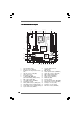
1.4 Motherboard Layout 5 3 4 2 1 7 6 22.1cm (8.
1.5 ASRock 6CH I/O 1 3 2 4 5 6 7 11 1 2 3 4 5 6 10 PS/2 Mouse Port (Green) Parallel Port USB 2.0 Ports (USB23) RJ-45 Port Line In (Light Blue) Line Out (Lime) 9 8 7 8 9 10 11 Microphone (Pink) USB 2.0 Ports (USB01) VGA Port COM Port PS/2 Keyboard Port (Purple) * To enable Multi-Streaming function, you need to connect a front panel audio cable to the front panel audio header. Please refer to below steps for the software setting of Multi-Streaming.
Chapter 2 Installation Wolfdale1333-D667 is a Micro ATX form factor (9.6" x 8.7", 24.4 x 22.1 cm) motherboard. Before you install the motherboard, study the configuration of your chassis to ensure that the motherboard fits into it. Make sure to unplug the power cord before installing or removing the motherboard. Failure to do so may cause physical injuries to you and damages to motherboard components. 2.1 Screw Holes Place screws into the holes indicated by circles to secure the motherboard to the chassis.
2.3 CPU Installation For the installation of Intel 775-LAND CPU, please follow the steps below. 775-Pin Socket Overview Before you insert the 775-LAND CPU into the socket, please check if the CPU surface is unclean or if there is any bent pin on the socket. Do not force to insert the CPU into the socket if above situation is found. Otherwise, the CPU will be seriously damaged. CPU Marked Corner Step 1. Open the socket: Step 1-1.
For proper inserting, please ensure to match the two orientation key notches of the CPU with the two alignment keys of the socket. Step 2-3. Carefully place the CPU into the socket by using a purely vertical motion. Step 2-4. Verify that the CPU is within the socket and properly mated to the orient keys. Step 3.
2.4 Installation of CPU Fan and Heatsink This motherboard is equipped with 775-Pin socket that supports Intel 775-LAND CPU. Please adopt the type of heatsink and cooling fan compliant with Intel 775-LAND CPU to dissipate heat. Before you installed the heatsink, you need to spray thermal interface material between the CPU and the heatsink to improve heat dissipation. Ensure that the CPU and the heatsink are securely fastened and in good contact with each other.
2.5 Installation of Memor y Modules (DIMM) Wolfdale1333-D667 motherboard provides two 240-pin DDR2 (Double Data Rate 2) DIMM slots, and supports Dual Channel Memory Technology. For dual channel configuration, you always need to install two identical (the same brand, speed, size and chip-type) memory modules in the DDR2 DIMM slots to activate Dual Channel Memory Technology. Otherwise, it will operate at single channel mode. 1.
2.6 Expansion Slots (PCI and PCI Express Slots) There are 2 PCI slots and 2 PCI Express slots on this motherboard. PCI slots: PCI slots are used to install expansion cards that have the 32-bit PCI interface. PCIE slots: PCIE1 (PCIE x16 slot) is used for PCI Express cards with x16 lane width graphics cards. PCIE2 (PCIE x1 slot) is used for PCI Express cards with x1 lane width cards, such as Gigabit LAN card, SATA2 card, etc.
2.7 Jumpers Setup The illustration shows how jumpers are setup. When the jumper cap is placed on pins, the jumper is “Short”. If no jumper cap is placed on pins, the jumper is “Open”. The illustration shows a 3-pin jumper whose pin1 and pin2 are “Short” when jumper cap is placed on these 2 pins. Jumper Setting PS2_USB_PWR1 2_3 1_2 Description Short pin2, pin3 to enable (see p.10 No. 1) +5VSB (standby) for PS/2 +5V +5VSB or USB wake up events.
2.8 Onboard Headers and Connectors Onboard headers and connectors are NOT jumpers. Do NOT place jumper caps over these headers and connectors. Placing jumper caps over the headers and connectors will cause permanent damage of the motherboard! FDD connector (33-pin FLOPPY1) (see p.10 No. 21) FLOPPY1 Pin1 the red-striped side to Pin1 Note: Make sure the red-striped side of the cable is plugged into Pin1 side of the connector. Primary IDE connector (Blue) (39-pin IDE1, see p.10 No.
USB 2.0 Headers USB_PWR P-4 P+4 GND DUMMY (9-pin USB4_5) (see p.10 No. 19) 1 GND P+5 P-5 USB_PWR (4-pin USB6) (see p.10 No. 20) Besides four default USB 2.0 ports on the I/O panel, there are two USB 2.0 headers on this motherboard. USB4_5 header can support two USB 2.0 ports, and USB6 header can support one USB 2.0 port. 1 GND P-6 P+6 USB_PWR WiFi Header USB+5V_2 NC NC (11-pin WIFI) (see p.10 No.
1. High Definition Audio supports Jack Sensing, but the panel wire on the chassis must support HDA to function correctly. Please follow the instruction in our manual and chassis manual to install your system. 2. If you use AC’97 audio panel, please install it to the front panel audio header as below: A. Connect Mic_IN (MIC) to MIC2_L. B. Connect Audio_R (RIN) to OUT2_R and Audio_L (LIN) to OUT2_L. C. Connect Ground (GND) to Ground (GND). D. MIC_RET and OUT_RET are for HD audio panel only.
Though this motherboard provides 4-Pin CPU fan (Quiet Fan) support, the 3-Pin CPU fan still can work successfully even without the fan speed control function. If you plan to connect the 3-Pin CPU fan to the CPU fan connector on this motherboard, please connect it to Pin 1-3. Pin 1-3 Connected 3-Pin Fan Installation ATX Power Connector (24-pin ATXPWR1) (see p.10, No. 28) 24 13 12 1 Please connect an ATX power supply to this connector.
2.9 SA SATTAII Hard Disk Setup Guide Before installing SATAII hard disk to your computer, please carefully read below SATAII hard disk setup guide. Some default setting of SATAII hard disks may not be at SATAII mode, which operate with the best performance. In order to enable SATAII function, please follow the below instruction with different vendors to correctly adjust your SATAII hard disk to SATAII mode in advance; otherwise, your SATAII hard disk may fail to run at SATAII mode.
2 . 1 0 Serial A ATTA (SA (SATTA) / Serial A ATTAII (SA (SATTAII) Hard Disks Installation This motherboard adopts Intel® ICH7 south bridge chipset that supports Serial ATA (SATA) / Serial ATAII (SATAII) hard disks. You may install SATA / SATAII hard disks on this motherboard for internal storage devices. This section will guide you to install the SATA / SATAII hard disks. STEP 1: Install the SATA / SATAII hard disks into the drive bays of your chassis.
Chapter 3 BIOS SETUP UTILITY 3.1 Introduction This section explains how to use the BIOS SETUP UTILITY to configure your system. The BIOS FWH chip on the motherboard stores the BIOS SETUP UTILITY. You may run the BIOS SETUP UTILITY when you start up the computer. Please press during the Power-On-Self-Test (POST) to enter the BIOS SETUP UTILITY, otherwise, POST will continue with its test routines.
3.1.2 Navigation Keys Please check the following table for the function description of each navigation key.
Main Advanced BIOS SETUP UTILITY H/W Monitor Boot Security Exit Configure CPU Advanced Settings WARNING : Setting wrong values in below sections may cause system to malfunction. CPU Configuration Chipset Configuration ACPI Configuration IDE Configuration PCIPnP Configuration Floppy Configuration SuperIO Configuration USB Configuration Enter F1 F9 F10 ESC Select Screen Select Item Go to Sub Screen General Help Load Defaults Save and Exit Exit v02.54 (C) Copyright 1985-2005, American Megatrends, Inc.
Ratio Status This is a read-only item, which displays whether the ratio status of this motherboard is “Locked” or “Unlocked”. If it shows “Unlocked”, you will find an item Ratio CMOS Setting appears to allow you changing the ratio value of this motherboard. Ratio Actual Value This is a read-only item, which displays the ratio actual value of this motherboard. Ratio CMOS Setting If the ratio status is unlocked, you will find this item appear to allow you changing the ratio value of this motherboard.
kernel version 2.4.18 or higher. This option will be hidden if the installed CPU does not support Hyper-Threading technology. Intel (R) SpeedStep(tm) tech. Intel (R) SpeedStep(tm) tech. is Intel’s new power saving technology. Processor can switch between multiple frequency and voltage points to enable power savings. The default value is [Auto]. Configuration options: [Auto], [Enabled] and [Disabled].
DRAM CAS# Latency Use this item to adjust the means of memory accessing. Configuration options are [6], [5], [4], [3] and [Auto]. DRAM RAS# to CAS# Delay This controls the latency between the DRAM active command and the read / write command. Configuration options: [2 DRAM Clocks], [3 DRAM Clocks], [4 DRAM Clocks], [5 DRAM Clocks], [6 DRAM Clocks] and [Auto]. DRAM RAS# Precharge This controls the idle clocks after a precharge command is issued.
DVMT/FIXED Memory You are allowed to adjust the shared memory size in this item if you set DVMT Mode Select as [DVMT Mode]. Configuration options: [64MB], [128MB] and [Maximum DVMT]. OnBoard HD Audio Select [Auto], [Enabled] or [Disabled] for the onboard HD Audio feature. If you select [Auto], the onboard HD Audio will be disabled when PCI Sound Card is plugged. Front Panel Select [Auto], [Enabled] or [Disabled] for the onboard HD Audio Front Panel.
3.3.3 ACPI Configuration BIOS SETUP UTILITY Advanced ACPI Configuration Suspend To RAM [Disabled] Restore on AC/Power Loss Ring-In Power On PCI Devices Power On PS / 2 Keyboard Power On RTC Alarm Power On [Power Off] [Disabled] [Disabled] [Disabled] [Disabled] ACPI HPET Table [Disabled] Select auto-detect or disable the STR feature. +F1 F9 F10 ESC Select Screen Select Item Change Option General Help Load Defaults Save and Exit Exit v02.54 (C) Copyright 1985-2005, American Megatrends, Inc.
3.3.4 IDE Configuration BIOS SETUP UTILITY Advanced IDE Configuration ATA/IDE Configuration SATAII 1 SATAII 2 SATAII 3 SATAII 4 IDE1 Master IDE1 Slave [Enhanced] [Hard Disk] [Not Detected] [Not Detected] [Not Detected] [ATAPI CDROM] [Not Detected] Set [Compatible] when Legacy OS (MS-DOS, Win NT) device is used. Set [Enhanced] when Native OS (Win2000 / XP) is used. +F1 F9 F10 ESC Select Screen Select Item Change Option General Help Load Defaults Save and Exit Exit v02.
BIOS SETUP UTILITY Advanced Primary IDE Master Device Vendor Size LBA Mode Block Mode PIO Mode Async DMA Ultra DMA S.M.A.R.T. :Hard Disk :ST340014A :40.0 GB :Supported :16Sectors :4 :MultiWord DMA-2 :Ultra DMA-5 :Supported Type LBA/Large Mode Block (Multi-Sector Transfer) PIO Mode DMA Mode S.M.A.R.T. 32Bit Data Transfer [Auto] [Auto] [Auto] [Auto] [Auto] [Disabled] [Enabled] Select the type of device connected to the system.
S.M.A.R.T. Use this item to enable or disable the S.M.A.R.T. (Self-Monitoring, Analysis, and Reporting Technology) feature. Configuration options: [Disabled], [Auto], [Enabled]. 32-Bit Data Transfer Use this item to enable 32-bit access to maximize the IDE hard disk data transfer rate. 3.3.5 PCIPnP Configuration BIOS SETUP UTILITY Advanced Advanced PCI / PnP Settings PCI Latency Timer PCI IDE BusMaster [32] [Enabled] Value in units of PCI clocks for PCI device latency timer register.
3.3.6 Floppy Configuration In this section, you may configure the type of your floppy drive. BIOS SETUP UTILITY Advanced Floppy Configuration [1.44 MB 31 2"] Floppy A Select the type of floppy drive connected to the system. +F1 F9 F10 ESC Select Screen Select Item Change Option General Help Load Defaults Save and Exit Exit v02.54 (C) Copyright 1985-2005, American Megatrends, Inc. 3.3.
Parallel Port Address Use this item to set the address for the onboard parallel port or disable it. Configuration options: [Disabled], [378], and [278]. Parallel Port Mode Use this item to set the operation mode of the parallel port. The default value is [ECP+EPP]. If this option is set to [ECP+EPP], it will show the EPP version in the following item, “EPP Version”. Configuration options: [Normal], [Bi-Directional], and [ECP+EPP]. EPP Version Use this item to set the EPP version. Configuration options: [1.
3.4 Hardware Health Event Monitoring Screen In this section, it allows you to monitor the status of the hardware on your system, including the parameters of the CPU temperature, motherboard temperature, CPU fan speed, chassis fan speed, and the critical voltage. Main Advanced BIOS SETUP UTILITY Boot H/W Monitor Hardware Health Event Monitoring CPU Temperature M / B Temperature : 37 C / 98 F : 31 C / 87 F CPU Fan Speed Chassis Fan Speed : 3400 RPM : N/A Vcore + 3.30V + 5.00V + 12.
3.5 Boot Screen In this section, it will display the available devices on your system for you to configure the boot settings and the boot priority. Main Advanced BIOS SETUP UTILITY H/W Monitor Boot Boot Settings Exit Configure Settings during System Boot.
3.6 Security Screen In this section, you may set or change the supervisor/user password for the system. For the user password, you may also clear it. Main Advanced BIOS SETUP UTILITY H/W Monitor Boot Security Settings Security Exit Install or Change the password. Supervisor Password : Not Installed User Password : Not Installed Change Supervisor Password Change User Password Enter F1 F9 F10 ESC Select Screen Select Item Change General Help Load Defaults Save and Exit Exit v02.
3.7 Exit Screen Main Advanced Exit Options Save Changes and Exit Discard Changes and Exit Discard Changes BIOS SETUP UTILITY H/W Monitro Boot Security Exit Exit system setup after saving the changes. F10 key can be used for this operation. Load Optimal Defaults Enter F1 F9 F10 ESC Select Screen Select Item Go to Sub Screen General Help Load Defaults Save and Exit Exit v02.54 (C) Copyright 1985-2005, American Megatrends, Inc.
Chapter 4 Software Suppor Supportt 4 . 1 Install Operating System This motherboard supports various Microsoft® Windows® operating systems: 2000 / XP / XP 64-bit / VistaTM / VistaTM 64-bit. Because motherboard settings and hardware options vary, use the setup procedures in this chapter for general reference only. Refer to your OS documentation for more information. 4 .