Version 1.0 Published November 2014 Copyright©2014 ASRock Rack Inc. All rights reserved. Copyright Notice: No part of this documentation may be reproduced, transcribed, transmitted, or translated in any language, in any form or by any means, except duplication of documentation by the purchaser for backup purpose, without written consent of ASRock Rack Inc.
Contact Information If you need to contact ASRock Rack or want to know more about ASRock Rack, you’re welcome to visit ASRock Rack’s website at www.ASRockRack.com; or you may contact your dealer for further information. ASRock Rack Incorporation 6F., No.37, Sec. 2, Jhongyang S. Rd., Beitou District, Taipei City 112, Taiwan (R.O.C.
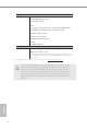
Contents Chapter 1 Introduction 1 1.1 Package Contents 1 1.2 Speciications 2 1.3 Unique Features 5 1.4 Motherboard Layout 6 1.5 I/O Panel 10 1.6 Block Diagram 12 Chapter 2 Installation 13 2.1 Screw Holes 13 2.2 Pre-installation Precautions 13 2.3 Installation of Memory Modules (DIMM) 14 2.4 Expansion Slots (PCI Express Slots) 16 2.5 Jumper Setup 17 2.6 Onboard Headers and Connectors 18 2.7 Unit Identiication purpose LED/Switch 23 2.
3.3.2 Storage Coniguration 29 3.3.3 ACPI Coniguration 30 3.3.4 Super IO Coniguration 31 3.4 H/W Monitor Screen (Hardware Health Event Monitoring) 36 3.5 IntelRCSetup 38 3.5.1 Processor Coniguration 39 3.5.2 North Bridge Coniguration 41 3.5.3 South Bridge Chipset Coniguration 42 3.5.4 System Event Log 44 3.6 Server Management 45 3.7 Event Logs 48 3.8 Security Screen 49 3.9 Boot Screen 50 3.10 Exit Screen 52 Chapter 4 Software Support 53 4.
5.3 Returning Merchandise for Service 56 Chapter 6: Net Framework Installation Guide 57 6.1 57 Installing .Net Framework 3.5.
C2X50D4I Series Chapter 1 Introduction hank you for purchasing ASRock Rack C2X50D4I Series motherboard, a reliable motherboard produced under ASRock Rack’s consistently stringent quality control. It delivers excellent performance with robust design conforming to ASRock Rack’s commitment to quality and endurance. In this manual, chapter 1 and 2 contains introduction of the motherboard and stepby-step guide to the hardware installation.
1.2 Speciications C2550D4I / C2750D4I / C2750D4I+ MB Physical Status Form Factor Mini-ITX Dimension 6.7'' x 6.7'' (17.0 cm x 17.0 cm) Processor System CPU C2750D4I / C2750D4I+: Intel® Octa Core Avoton C2750 Processor C2550D4I: Intel® Octa Core Avoton C2550 Processor FCBGA1283 SOC English Socket System Memory Max.
C2X50D4I Series Gracphics Controller VRAM Output Rear Panel I/O VGA Port USB 2.0 Port LAN Port Serial Port ASPEED AST2300 DDR3 16MB Supports D-Sub with max.
Support OS OS Microsot® Windows® - Server 2008 R2 SP1 (64 bit) - Server 2012 (64 bit) Linux® - CentOS 6.4/5.10 (x32 and x64) (only support AHCI mode) - SUSE Enterprise Linux Server 11 SP1 (32 / 64 bit) - FreeBSD 9.1 (32 / 64 bit) - Fedora Core 19 (64 bit) - Ubuntu 12.04/12.10 (64 bit) Virtual: - VMWare ESXi 5.
C2X50D4I Series 1.3 Unique Features ASRock Instant Flash is a BIOS lash utility embedded in Flash ROM. his convenient BIOS update tool allows you to update system BIOS without entering operating systems irst like MS-DOS or Windows®. With this utility, you can press the key during the POST or the key to enter into the BIOS setup menu to access ASRock Rack Instant Flash.
1.4 Motherboard Layout C2750D4I 1 17.0cm (6.7 in) ATXPWR1 COM1 VGA1 DDR3_A2 (64 bit, 240-pin module) 2 DDR3_A1 (64 bit, 240-pin module) 3 Top: IPMI LAN REAR_FAN2 REAR_FAN1 4 LAN2 LAN1 CPU_FAN2 CPU_FAN1 64Mb BIOS UID_SW_LED1 17.0cm (6.7 in) USB 2.
C2X50D4I Series C2750D4I+ 1 17.0cm (6.7 in) ATXPWR1 COM1 VGA1 DDR3_A2 (64 bit, 240-pin module) 2 DDR3_A1 (64 bit, 240-pin module) 3 Top: IPMI LAN REAR_FAN2 REAR_FAN1 4 LAN2 LAN1 CPU_FAN2 CPU_FAN1 17.0cm (6.7 in) USB 2.
C2550D4I 1 17.0cm (6.7 in) ATXPWR1 COM1 VGA1 DDR3_A2 (64 bit, 240-pin module) 2 DDR3_A1 (64 bit, 240-pin module) 3 Top: IPMI LAN REAR_FAN2 REAR_FAN1 4 LAN2 LAN1 CPU_FAN2 CPU_FAN1 64Mb BIOS UID_SW_LED1 17.0cm (6.7 in) USB 2.
C2X50D4I Series Description 1 ATX Power Connector (ATXPWR1) 2 2 x 240-pin DDR3 DIMM Slots (DDR3_A1, DDR3_A2) 3 Rear Fan Connector (REAR_FAN1) 4 Rear Fan Connector (REAR_FAN2) 5 CPU Fan Connector (CPU_FAN1) 6 CPU Fan Connector (CPU_FAN2) 7 2 x 240-pin DDR3 DIMM Slots (DDR3_B1, DDR3_B2) 8 SATA3 Connector (SATA3_M0, White) 9 SATA3 Connector (SATA3_M1, White) 10 USB Selection Jumper (USB_SEL1) 11 SATA3 Connector (SATAIII_M0, White) 12 SATA3 Connector (SATAIII_M1, White) 13 System Pane
1.5 I/O Panel C2550D4I / C2750D4I / C2750D4I+ 1 3 5 2 4 6 7 No. Description No. Description 1 Serial Port (COM1) 5 2 D-Sub Port (VGA1) 6 LAN RJ-45 Port (LAN2)** 3 Dedicated IPMI LAN Port* 7 UID Switch/LED (UID_SW_LED1) 4 USB 2.0 Ports (USB_0-1) LAN RJ-45 Port (LAN1)** LAN Port LED Indications *here are two LED next to the LAN port. Please refer to the table below for the LAN port LED indications.
C2X50D4I Series **here are two LEDs on each LAN port. Please refer to the table below for the LAN port LED indications.
English 12 1.
C2X50D4I Series Chapter 2 Installation This is a Mini-ITX form factor (6.7'' x 6.7'', 17.0 cm x 17.0 cm) motherboard. Before you install the motherboard, study the coniguration of your chassis to ensure that the motherboard its into it. Make sure to unplug the power cord before installing or removing the motherboard. Failure to do so may cause physical injuries to you and damages to motherboard components. 2.
2.3 Installation of Memory Modules (DIMM) his motherboard provides four 240-pin DDR3 (Double Data Rate 3) DIMM slots, and supports Dual Channel Memory Technology. 1. For dual channel coniguration, you always need to install identical (the same brand, speed, size and chip-type) DDR3 DIMM pairs. 2. It is unable to activate Dual Channel Memory Technology with only one or three memory module installed. 3.
C2X50D4I Series 1 2 English 3 15
2.4 Expansion Slots (PCI Express Slots) here is 1 PCI Express slots on this motherboard. PCIE slot: PCIE1 (PCIE 2.0 x8 slot) is used for PCI Express x8 lane width graphics cards. Installing an expansion card Step 1. Step 2. Step 3. Step 4. Step 5. Step 6. English 16 Before installing an expansion card, please make sure that the power supply is switched of or the power cord is unplugged.
C2X50D4I Series 2.5 Jumper Setup he illustration shows how jumpers are setup. When the jumper cap is placed on the pins, the jumper is “Short”. If no jumper cap is placed on the pins, the jumper is “Open”. he illustration shows a 3-pin jumper whose pin1 and pin2 are “Short” when a jumper cap is placed on these 2 pins. USB Selection Jumper (3-pin USB_SEL1) (No. 10) (3-pin USB_SEL2) (No. 19) Support: Rear USB 2.0 ports x 1 Front USB header x 2 English Support: Rear USB 2.
2.6 Onboard Headers and Connectors Onboard headers and connectors are NOT jumpers. Do NOT place jumper caps over these headers and connectors. Placing jumper caps over the headers and connectors will cause permanent damage to the motherboard. *You can see p.6 or p.7 for motherboard layout. Serial ATA3 Connectors (SATA_0: No. 32) (SATA_1: No. 31) (SATA3_M0: No. 8) (SATA3_M1: No. 9) (SATAIII_M0: No. 11) (SATAIII_M1: No. 12) (SATAIII_M2: No. 14) (SATAIII_M3: No.
GND LAD0 SERIRQ# GND +3V S_PWRDWN# LAD2 LAD1 LAD3 SMB_CLK_MAIN SMB_DATA_MAIN GND FRAME TPM Header (17-pin TPMS1) (No. 18) PCICLK C2X50D4I Series System Panel Header (9-pin PANEL1) (No. 13) PLED+ PLEDPWRBTN# GND 1 GND +3VSB PCIRST# 1 his connector supports Trusted Platform Module (TPM) system, which can securely store keys, digital certiicates, passwords, and data. A TPM system also helps enhance network security, protects digital identities, and ensures platform integrity.
LED_PWR LAN2_LINK LOCATORLED2- LOCATORLED2+ LAN1_LINK LED_PWR LOCATORBTN# GND +5VSB LOCATORLED1- GND 12C_4_DATA# B LOCATORLED1+ NC A 12C_4_CLK# Auxiliary Panel Header (18-pin AUX_PANEL1) (No. 14) his header supports multiple functions on the front panel, including front panel SMB, internet status indicator. NC GND +5VSB 1 C A. Front panel SMBus connecting pin (6-1 pin FPSMB) his header allows you to connect SMBus (System Management Bus) equipment.
C2X50D4I Series CPU Fan Connectors (4-pin CPU_FAN1) (No. 5) 1 (4-pin CPU_FAN2) (No. 6) 1 GND 2 +12V 3 FAN_SPEED 4 FAN_SPEED_CONTROL GND +12V 2 3 4 Please connect the CPU fan cable to the connector and match the black wire to the ground pin. hough this motherboard provides a 4-Pin CPU fan (Quiet Fan) connector, 3-Pin CPU fans can still work successfully even without the fan speed control function.
Non Maskable Interrupt Button Header (2-pin NMI_BTN1) (see p.13 or 15, No. 21) BMC SMB Headers (5-pin BMC_SMB_1) (No. 26) (5-pin BMC_SMB_2) (No. 25) (5-pin BMC_SMB_3) (No. 20) English 22 POWER 1 CONTROL Please connect a NMI device to this header. his header is used for the SM BUS devices.
C2X50D4I Series 2.7 Unit Identiication purpose LED/Switch With the UID button, You are able to locate the server you’re working on from behind a rack of servers. Unit Identiication purpose LED/Switch (UID_SW_LED1) When the UID button on the front or rear panel is pressed, the front/rear UID blue LED indicator will be turned on. Press the UID button again to turn of the indicator. 2.
Chapter 3 UEFI Setup Utility 3.1 Introduction his section explains how to use the UEFI SETUP UTILITY to conigure your system. he UEFI chip on the motherboard stores the UEFI SETUP UTILITY. You may run the UEFI SETUP UTILITY when you start up the computer. Please press or during the Power-On-Self-Test (POST) to enter the UEFI SETUP UTILITY; otherwise, POST will continue with its test routines.
C2X50D4I Series 3.1.2 Navigation Keys Please check the following table for the function description of each navigation key.
3.2 Main Screen Once you enter the UEFI SETUP UTILITY, the Main screen will appear and display the system overview. he Main screen provides system overview information and allows you to set the system time and date.
C2X50D4I Series 3.3 Advanced Screen In this section, you may set the conigurations for the following items: Easy RAID Installer, Storage Coniguration, ACPI Coniguration, Super IO Coniguration, Serial Port Console Redirection, PCI Subsystem Settings, PLX 8608 Coniguration, Voltage and Instant Flash. Setting wrong values in this section may cause the system to malfunction. Instant Flash English Instant Flash is a UEFI lash utility embedded in Flash ROM.
3.3.1 Easy Raid Installer Easy RAID Installer can help you to copy the RAID driver from a support CD to your USB storage device. Ater copying the RAID driver to your USB storage device, please change “SATA Mode” to “RAID”, then you can start installing the OS in RAID mode.
C2X50D4I Series 3.3.2 Storage Coniguration Hard Disk S.M.A.R.T. Use this item to enable or disable the S.M.A.R.T. (Self-Monitoring, Analysis, and Reporting Technology) feature. Marvell 9230 SATA3_M0~M3 Operation This item is for Marvell 9230 SATA3_M0~M3 ports. Use this to select Marvell SATA3 mode. Coniguration options: [Enabled] and [Disabled]. he default value is [Enabled]. Bootable Marvell 9230 SATAIII Use this to enable or disable Marvell SATA Boot ROM.
3.3.3 ACPI Coniguration ACPI HPET Table Enable the High Precision Event Timer for better performance. PCIE Devices Power On Use this item to enable or disable PCIE devices to turn on the system from the power-sotof mode. RTC Alarm Power On Use this item to enable or disable RTC (Real Time Clock) to power on the system.
C2X50D4I Series 3.3.4 Super IO Coniguration Deep Sleep Use this to conigure Deep Sleep. he default value is [Disabled]. Serial Port 1 Coniguration Use this item to conigure the onboard serial port 1. SOL Coniguration English Use this item to conigure the onboard serial port 2.
3.3.5 Serial Port Console Redirection Console Redirection Use this option to enable or disable Console Redirection.
C2X50D4I Series 3.3.6 PCI Subsystem Settings Above 4G Decoding English Use this option to enable or disable 64bit capable devices to be decoded in above 4G address space (only if system supports 64bit PCI decoding).
3.3.7 PLX 8608 Coniguration Primary Graphics Adapter his allows you to select [Onboard] or [PCI Express] as the boot graphic adapter priority. he default value is [PCI Express]. Onboard VGA his allows you to enable or disable the Onboard VGA feature. Onboard LAN1 his allows you to enable or disable the Onboard LAN1 feature. Onboard LAN2 his allows you to enable or disable the Onboard LAN2 feature.
C2X50D4I Series 3.3.8 Voltage DRAM Voltage English Use this to select DRAM Voltage. he default value is [Auto].
3.4 H/W Monitor Screen (Hardware Health Event Monitoring) In this section, it allows you to monitor the status of the hardware on your system, including the parameters of the CPU temperature, motherboard temperature and the critical voltage. CPU_FAN1 Setting his allows you to set the speed of CPU fan 1. he default value is [Smart Fan]. CPU_FAN2 Setting his allows you to set the speed of CPU fan 2. he default value is [Smart Fan]. REAR_FAN1 Setting his allows you to set the speed of REAR Fan 1.
C2X50D4I Series Watch Dog Timer English his allows you to enable or disable the Watch Dog Timer. he default value is [Disabled].
3.5 IntelRCSetup In this section, you may set the conigurations for the following items: Processor Coniguration, North Bridge Chipset Coniguration, South Bridge Chipset Coniguration and System Event Log.
C2X50D4I Series 3.5.1 Processor Coniguration Intel SpeedStep Technology Intel SpeedStep technology is Intel’s new power saving technology. Processors can switch between multiple frequencies and voltage points to enable power saving. he default value is [Enabled]. Coniguration options: [Enabled] and [Disabled]. his item will be hidden if the current CPU does not support Intel SpeedStep technology.
Intel Turbo Boost Technology Use this item to enable or disable Intel Turbo Boost Mode Technology. Turbo Boost Mode allows processor cores to run faster than marked frequency in speciic conditions. he default value is [Enabled]. Active Processor Cores Use this item to select the number of cores to enable in each processor package. he default value is [All].
C2X50D4I Series 3.5.2 North Bridge Coniguration Fast Boot Use this item to enable to disable fast boot which skips memory training and attempts to boot using last known good coniguration. DRAM Frequency If [Auto] is selected, the motherboard will detect the memory module(s) inserted and assign the appropriate frequency automatically. ECC Support English Use this item to enable or disable DDR ECC Support.
3.5.3 South Bridge Chipset Coniguration Restore on AC/Power Loss Select the power state ater a power failure. If [Power Of] is selected, the power will remain of when the power recovers. If [Power On] is selected, the system will start to boot up when the power recovers.
C2X50D4I Series SATA 2 Controller / SATA 3 Controller Use this item to enable or disable SATA Controller. SATA Mode Selection Use this to select SATA mode. Configuration options: [Disabled], [IDE Mode], [AHCI Mode] and [RAID Mode]. he default value is [AHCI Mode]. AHCI (Advanced Host Controller Interface) supports NCQ and other new features that will improve SATA disk performance but IDE mode does not have these advantages.
3.5.4 System Event Log Whea Settings Use this option to conigure Windows Hardware Error Architecture.
C2X50D4I Series 3.6 Server Management Wait For BMC Wait For BMC response for speciied time out. In PILOTII, BMC starts at the same time when BIOS starts during AC power ON. It takes around 30 seconds to initialize Host to BMC interfaces. System Event Log Enter to conigure System Event Logging features during boot. BMC Network Coniguration Press to conigure BMC Network parameters. Coniguration Address Source Select to conigure BMC network parameters statically or dynamically(by BIOS or BMC).
To configure BMC network parameters using the BIOS setup, select either [Static] or [Dynamic] option. To conigure BMC network parameters using the BMC web interface, select [Unspeciied] option. When [Dynamic] or [Static] is selected, do NOT modify the BMC network settings on the IPMI web page. BMC Mac Backup Tool Use this to restore BMC Mac from the backup.
C2X50D4I Series Please refer to the table below for the LAN interface mapping to check the MAC address through either BIOS or Web interface.
3.7 Event Logs Change Smbios Event Log Settings his allows you to conigure the Smbios Event Log Settings. View Smbois Event Log his allows you to view the Smbios Event Log.
C2X50D4I Series 3.8 Security Screen In this section, you may set or change the supervisor/user password for the system. For the user password, you may also clear it. Supervisor Password Set or change the password for the administrator account. Only the administrator has authority to change the settings in the UEFI Setup Utility. Leave it blank and press enter to remove the password. User Password English Set or change the password for the user account.
3.9 Boot Screen In this section, it will display the available devices on your system for you to conigure the boot settings and the boot priority. Boot Option #1 Use this item to set the system boot order. Setup Prompt Timeout his shows the number of seconds to wait for setup activation key. Bootup Num-Lock If this item is set to [On], it will automatically activate the Numeric Lock function ater boot-up. PCI ROM Priority Use this item to adjust PCI ROM Priority.
C2X50D4I Series [Enabled]. Coniguration options: [Enabled] and [Disabled]. he default value is [Enabled]. Boot From Onboard LAN Use this item to enable or disable the Boot From Onboard LAN feature. CSM Parameters Use this option to conigure the parameters of OpROM execution, boot options ilter, etc. Boot Option Filter Use this option to control what devices system can boot to. Coniguration options: [UEFI and Legacy], [Legacy only] and [UEFI only].
3.10 Exit Screen Save Changes and Exit When you select this option, the following message “Save coniguration changes and exit setup?” will pop-out. Select [Yes] to save the changes and exit the UEFI SETUP UTILITY. Discard Changes and Exit When you select this option, the following message “Discard changes and exit setup?” will pop-out. Select [Yes] to exit the UEFI SETUP UTILITY without saving any changes. Discard Changes When you select this option, the following message “Discard changes?” will pop-out.
C2X50D4I Series Chapter 4 Software Support 4.1 Install Operating System his motherboard supports Microsot® Windows® Server 2008 R2 SP1 (64 bit) / 2012 (64 bit) / Linux compliant. Because motherboard settings and hardware options vary, use the setup procedures in this chapter for general reference only. Refer your OS documentation for more information. *Please download the Intel ® SATA Floppy Image driver from the ASRock Rack’s website (www.asrockrack.
Chapter 5 Troubleshooting 5.1 Troubleshooting Procedures Follow the procedures below to troubleshoot your system. Always unplug the power cord before adding, removing or changing any hardware components. Failure to do so may cause physical injuries to you and damages to motherboard components. 1. Disconnect the power cable and check whether the PWR LED is of. 2. Unplug all cables, connectors and remove all add-on cards from the motherboard. Make sure that the jumpers are set to default settings. 3.
C2X50D4I Series Unable to save system setup conigurations... 1. Verify if the battery on the motherboard provides ~3VDC. Install a new battery if it does not. 2. Conirm whether your power supply provides adaquate and stable power. Other problems... English 1. Try searching keywords related to your problem on ASRock Rack’s FAQ page: http://www.asrockrack.
5.2 Technical Support Procedures If you have tried the troubleshooting procedures mentioned above and the problems are still unsolved, please contact ASRock Rack’s technical support with the following information: 1. 2. 3. 4. Your contact information Model name, BIOS version and problem type System coniguration Problem description You may contact ASRock Rack’s technical support at: http://www.asrockrack.com/support/tsd.asp 5.
C2X50D4I Series Chapter 6: Net Framework Installation Guide To let Intel® RSTe works properly, it is required to install Net Framework. Please follow the steps below to enable “.Net Framework” feature on Microsot® Windows® Server 2008 R2. 6.1 Installing .Net Framework 3.5.1 (For Server 2008 R2) 1. Double-click the Server Manager icon in the Windows system tray. English 2. Click Add Features in the right hand pane.
3. Check the box next to .Net Framework 3.5.1 and then click Next. 4. Click Next to continue.
5. Click Install to start installing .Net Framework 3.5.1. 6. Ater the installation completes, click Close.