ConRoe865PE User Manual Version 3.1 Published May 2006 Copyright©2005 ASRock INC. All rights reserved.
Copyright Notice: No part of this manual may be reproduced, transcribed, transmitted, or translated in any language, in any form or by any means, except duplication of documentation by the purchaser for backup purpose, without written consent of ASRock Inc. Products and corporate names appearing in this manual may or may not be registered trademarks or copyrights of their respective companies, and are used only for identification or explanation and to the owners’ benefit, without intent to infringe.
Contents 1 Introduction ................................................... ... 5 1.1 1.2 1.3 1.4 Package Contents................................................................ 5 Specifications ..................................................................... 6 Motherboard Layout ........................................................... 9 ASRock 8CH I/O .................................................................. 10 2 Installation ............................................. 11 2.
Software Support ........................................... 39 4.1 Install Operating System ............................................... 4.2 Support CD Information ................................................. 4.2.1 Running Support CD ............................................ 4.2.2 Drivers Menu ........................................................ 4.2.3 Utilities Menu ........................................................ 4.2.4 “LGA 775 CPU Installation Live Demo” Program ..
Chapter 1 Introduction Thank you for purchasing ASRock ConRoe865PE motherboard, a reliable motherboard produced under ASRock’s consistently stringent quality control. It delivers excellent performance with robust design conforming to ASRock’s commitment to quality and endurance. In this manual, chapter 1 and 2 contain introduction of the motherboard and step-bystep guide to the hardware installation. Chapter 3 and 4 contain the configuration guide to BIOS setup and information of the Support CD.
1.2 Specifications Platform CPU Chipset Memory Hybrid Booster Expansion Slot Audio LAN Rear Panel I/O 6 - ATX Form Factor: 12.0-in x 9.0-in, 30.5 cm x 22.
Connector BIOS Feature Support CD Hardware Monitor OS Certifications - 2 x Serial ATA 1.5Gb/s connectors (No Support for RAID and “Hot Plug” functions) - 2 x ATA100 IDE connectors (support 4 x IDE devices) - 1 x Floppy connector - 1 x IR header - 1 x Game header - CPU/Chassis FAN connector - 20 pin ATX power connector - 4 pin 12V power connector - CD in header - Front panel audio connector - 2 x USB 2.0 headers (support 4 USB 2.
CAUTION! 1. To support FSB1066 CPU, please use DDR400 DIMMs (Double Data Rate 400 MHz). Before installing FSB1066 CPU, please make sure that you have adjusted the jumpers correctly. The default setting of FSB1 is to short pin1 and pin2. However, if you want this motherboard to support FSB1066 CPU, please adjust your FSB1 jumper setting, and short pin2 2. and pin3 (see page 18). About the setting of “Hyper Threading Technology”, please check page 26. 3.
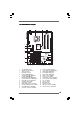
1.3 Motherboard Layout 1 2 4 3 56 22.9cm (9.0 in) 1 PS2 Mouse PS2_USB_PWR1 AGP 8X 27 FSB1 Intel ICH5 PCI 2 ConRoe865PE PCI LAN SATA CMOS Battery CLRCMOS0 PCI 4 AUDIO CODEC 1 USB67 USB45 PCI 5 JR1 JL1 30.5cm (12.0 in) 11 12 13 14 PANEL 1 PLED PWRBTN 1 AUDIO1 23 7 8 9 10 11 12 13 14 SATA1 SATA2 USB2.0 1 6 10 ` RoHS PCI 3 25 1 2 3 4 5 IDE2 9 1 PCI 1 7.1CH 24 DDR3 (64/72 bit, 184-pin module) 8 1.
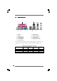
1.4 ASRock 8CH I/O 1 13 1 2 3 4 5 6 *7 2 11 12 10 Parallel Port RJ-45 Port Side Speaker (Gray) Rear Speaker (Black) Central / Bass (Orange) Line In (Light Blue) 8 9 10 11 12 13 3 6 4 7 5 8 9 Microphone (Pink) USB 2.0 Ports (USB01) USB 2.0 Ports (USB23) Serial Port: COM1 PS/2 Keyboard Port (Purple) PS/2 Mouse Port (Green) Front Speaker (Lime) * If you use 2-channel speaker, please connect the speaker’s plug into “Front Speaker Jack”.
Chapter 2 Installation ConRoe865PE is an ATX form factor (12.0" x 9.0", 30.5 x 22.9 cm) motherboard. Before you install the motherboard, study the configuration of your chassis to ensure that the motherboard fits into it. Make sure to unplug the power cord before installing or removing the motherboard. Failure to do so may cause physical injuries to you and damages to motherboard components. 2.1 Screw Holes Place screws into the holes indicated by circles to secure the motherboard to the chassis.
2.3 CPU Installation For the installation of Intel 775-LAND CPU, please follow the steps below. 775-Pin Socket Overview Before you insert the 775-LAND CPU into the socket, please check if the CPU surface is unclean or if there is any bent pin on the socket. Do not force to insert the CPU into the socket if above situation is found. Otherwise, the CPU will be seriously damaged. CPU Marked Corner Step 1. Open the socket: Step 1-1.
For proper inserting, please ensure to match the two orientation key notches of the CPU with the two alignment keys of the socket. Step 2-3. Carefully place the CPU into the socket by using a purely vertical motion. Step 2-4. Verify that the CPU is within the socket and properly mated to the orient keys. Step 3.
2.4 Installation of CPU Fan and Heatsink This motherboard is equipped with 775-Pin socket that supports Intel 775-LAND CPU. Please adopt the type of heatsink and cooling fan compliant with Intel 775-LAND CPU to dissipate heat. Before you installed the heatsink, you need to spray thermal interface material between the CPU and the heatsink to improve heat dissipation. Ensure that the CPU and the heatsink are securely fastened and in good contact with each other.
2.5 Installation of Memory Modules (DIMM) ConRoe865PE motherboard provides four 184-pin DDR (Double Data Rate) DIMM slots, and supports Dual Channel Memory Technology. For dual channel configuration, you always need to install identical (the same brand, speed, size and chip-type) DDR DIMM pair in the slots of the same color. In other words, you have to install identical DDR DIMM pair in Dual Channel A (DDR1 and DDR3; Blue slots; see p.9 No.
Installing a DIMM Please make sure to disconnect power supply before adding or removing DIMMs or the system components. Step 1. Step 2. Unlock a DIMM slot by pressing the retaining clips outward. Align a DIMM on the slot such that the notch on the DIMM matches the break on the slot. notch break notch break The DIMM only fits in one correct orientation. It will cause permanent damage to the motherboard and the DIMM if you force the DIMM into the slot at incorrect orientation. Step 3.
2.6 Expansion Slots (PCI and AGP Slots) There are 5 PCI slots and 1 AGP slot on ConRoe865PE motherboard. PCI slots: PCI slots are used to install expansion cards that have the 32-bit PCI interface. AGP slot: The AGP slot is used to install a graphics card. The AGP slot has a special design of clasp that can securely fasten the inserted graphics card. Please do NOT use a 3.
2.7 Jumpers Setup The illustration shows how jumpers are setup. When the jumper cap is placed on pins, the jumper is “Short”. If no jumper cap is placed on pins, the jumper is “Open”. The illustration shows a 3-pin jumper whose pin1 and pin2 are “Short” when jumper cap is placed on these 2 pins. Jumper FSB1 Setting (see p.9 item 9) 1_2 1_2 FSB 533MHz FSB 800MHz PS2_USB_PWR1 2_3 FSB 1066MHz Description “NORMAL” (short pin1, pin2) is the default setting for the FSB jumper.
2.8 Onboard Headers and Connectors Onboard headers and connectors are NOT jumpers. Do NOT place jumper caps over these headers and connectors. Placing jumper caps over the headers and connectors will cause permanent damage of the motherboard! FDD connector (33-pin FLOPPY1) Pin1 (see p.9 No. 20) FLOPPY1 the red-striped side to Pin1 Note: Make sure the red-striped side of the cable is plugged into Pin1 side of the connector.
Serial ATA (SATA) Power Cable (Optional) connect to the power supply connect to the SATA HDD power connector USB_PWR P-6 P+6 GND DUMMY USB 2.0 Header (9-pin USB67) (see p.9 No. 17) 1 GND P+7 P-7 USB_PWR USB 2.0 Header USB_PWR P-5 P+5 GND DUMMY (9-pin USB45) (see p.9 No. 19) 1 GND P+4 P-4 USB_PWR IRTX +5VSB DUMMY Infrared Module Header (5-pin IR1) (see p.9 No. 18) 1 GND IRRX Internal Audio Connectors (4-pin CD1) CD-L GND GND CD-R (CD1: see p.9 No.
PLED+ PLEDPWRBTN# GND System Panel Header (9-pin PANEL1) (see p.9 No. 15) 1 This header accommodates several system front panel functions. DUMMY RESET# GND HDLEDHDLED+ Chassis Speaker Header 1 SPEAKER DUMMY DUMMY +5V (4-pin SPEAKER 1) (see p.9 No. 16) Chassis Fan Connector GND +12V CHA_FAN_SPEED (3-pin CHA_FAN1) (see p.9 No. 14) CPU Fan Connector GND +12V CPU_FAN_SPEED FAN_SPEED_CONTROL (4-pin CPU_FAN1) (see p.9 No. 29) ATX Power Connector Please connect the chassis speaker to this header.
2.9 Serial A ATTA (SA (SATTA) Hard Disks Installation This motherboard adopts Intel® ICH5 south bridge chipset that supports Serial ATA (SATA) hard disks. You may install SATA hard disks on this motherboard for internal storage devices. This section will guide you to install the SATA hard disks. STEP 1: Install the SATA hard disks into the drive bays of your chassis. STEP 2: Connect the SATA power cable to the SATA hard disk.
Chapter 3 BIOS SETUP UTILITY 3.1 Introduction This section explains how to use the BIOS SETUP UTILITY to configure your system. The BIOS FWH chip on the motherboard stores the BIOS SETUP UTILITY. You may run the BIOS SETUP UTILITY when you start up the computer. Please press during the Power-On-Self-Test (POST) to enter the BIOS SETUP UTILITY, otherwise, POST will continue with its test routines.
3.1.2 Navigation Keys Please check the following table for the function description of each navigation key. Navigation Key(s) / / + / 3.
Main BIOS SETUP UTILITY H/W Monitor Boot Advanced Security Exit Configure CPU Advanced Settings WARNING : Setting wrong values in below sections may cause system to malfunction. CPU Configuration Chipset Configuration ACPI Configuration IDE Configuration PCIPnP Configuration Floppy Configuration SuperIO Configuration USB Configuration Enter F1 F9 F10 ESC Select Screen Select Item Go to Sub Screen General Help Load Defaults Save and Exit Exit v02.54 (C) Copyright 1985-2003, American Megatrends, Inc.
Ratio Actual Value This is a read-only item, which displays the ratio actual value of this motherboard. Ratio CMOS Setting If the ratio status is unlocked, you will find this item appear to allow you changing the ratio value of this motherboard. Enhance Halt State All processors support the Halt State (C1). The C1 state is supported through the native processor instructions HLT and MWAIT and requires no hardware support from the chipset.
3.3.2 Chipset Configuration BIOS SETUP UTILITY Advanced Chipset Configuration Bypass Access DRAM Frequency Flexibility Option Configure DRAM Timing by SPD DRAM CAS# Latency DRAM RAS# Precharge DRAM RAS# to CAS# Delay DRAM Precharge Delay DRAM Burst Length Options [Off] [Auto] [Disabled] [Disabled] [Auto] [4] [4] [8] [4] Init.
DRAM Burst Length DRAM Burst length can be set as [8] or [4]. Init. Graphic Adapter Priority This allows you to select [PCI/AGP] and [AGP/PCI] as the initial graphics adapter priority. The default vaule is [PCI/AGP]. Graphics Aperture Size It refers to a section of the PCI memory address range used for graphics memory. It is recommended to leave this field at the default value unless the installed AGP card’s specifications requires other sizes.
RTC Alarm Power On Use this item to enable or disable RTC (Real Time Clock) to power on the system. 3.3.4 IDE Configuration BIOS SETUP UTILITY Advanced IDE Configuration OnBoard IDE Operate Mode OnBoard IDE Controller Primary IDE Master Primary IDE Slave Secondary IDE Master Secondary IDE Slave SATA1 SATA2 [Enhanced Mode] [Both] [Hard Disk] [Not Detected] [Not Detected] [Not Detected] [Not Detected] [Not Detected] Set [Compatible Mode] when both Legacy OS (MS-DOS, Win Me / 98SE) and SATA device are used.
Because Intel® ICH5 south bridge only supports four IDE devices under legacy OS (Windows ME / 98SE), you have to choose either [Pri IDE + SATA] or [SATA + Sec IDE] when the installed SATA device is used with legacy OS. IDE Device Configuration You may set the IDE configuration for the device that you specify.
Block (Multi-Sector Transfer) The default value of this item is [Auto]. If this feature is enabled, it will enhance hard disk performance by reading or writing more data during each transfer. PIO Mode Use this item to set the PIO mode to enhance hard disk performance by optimizing the hard disk timing. DMA Mode DMA capability allows the improved transfer-speed and data-integrity for compatible IDE devices. S.M.A.R.T. Use this item to enable or disable the S.M.A.R.T.
3.3.6 Floppy Configuration In this section, you may configure the type of your floppy drive. BIOS SETUP UTILITY Advanced Floppy Configuration [1.44 MB 31 2"] Floppy A Select the type of floppy drive connected to the system. +F1 F9 F10 ESC Select Screen Select Item Change Option General Help Load Defaults Save and Exit Exit v02.54 (C) Copyright 1985-2003, American Megatrends, Inc. 3.3.
Parallel Port Address Use this item to set the address for the onboard parallel port or disable it. Configuration options: [Disabled], [378], and [278]. Parallel Port Mode Use this item to set the operation mode of the parallel port. The default value is [ECP+EPP]. If this option is set to [ECP+EPP], it will show the EPP version in the following item, “EPP Version”. Configuration options: [Normal], [Bi-Directional], and [ECP+EPP]. EPP Version Use this item to set the EPP version. Configuration options: [1.
3.3.8 USB Configuration BIOS SETUP UTILITY Advanced USB Configuration USB Controller USB 2.0 Support Legacy USB Support [Enabled] [Enabled] [Disabled] To enable or disable the onboard USB controllers. +F1 F9 F10 ESC Select Screen Select Item Change Option General Help Load Defaults Save and Exit Exit v02.54 (C) Copyright 1985-2003, American Megatrends, Inc. USB Controller Use this item to enable or disable the use of USB controller. USB 2.0 Support Use this item to enable or disable the USB 2.
3.4 Hardware Health Event Monitoring Screen In this section, it allows you to monitor the status of the hardware on your system, including the parameters of the CPU temperature, motherboard temperature, CPU fan speed, chassis fan speed, and the critical voltage. Main Advanced BIOS SETUP UTILITY Boot H/W Monitor Security Exit Hardware Health Event Monitoring CPU Temperature M / B Temperature : 45 C / 98 F : 31 C / 87 F CPU Fan Speed Chassis Fan Speed : 2463 RPM : N/A Vcore + 3.30V + 5.00V + 12.
3.5 Boot Screen In this section, it will display the available devices on your system for you to configure the boot settings and the boot priority. Main Advanced BIOS SETUP UTILITY H/W Monitor Boot Boot Settings Security Exit Configure Settings during System Boot. Boot Settings Configuration Boot Device Priority Hard Disk Drives Removable Drives CD/DVD Drives Enter F1 F9 F10 ESC Select Screen Select Item Go to Sub Screen General Help Load Defaults Save and Exit Exit v02.
3.5.2 Boot Device Priority In this section, you may specify the boot sequence from the available devices in your system. BIOS SETUP UTILITY Boot Boot Device Priority 1st Boot Device 2nd Boot Device 3rd Boot Device [1st FLOPPY DRIVE] [HDD: PM-MAXTOR 6L08] [CD / DVD] Specifies the boot sequence from the available devices. A device enclosed in parenthesis has been disabled in the corresponding type menu.
3.7 Exit Screen Main Advanced Exit Options Save Changes and Exit Discard Changes and Exit Discard Changes BIOS SETUP UTILITY H/W Monitro Boot Security Exit Exit system setup after saving the changes. F10 key can be used for this operation. Load Optimal Defaults Enter F1 F9 F10 ESC Select Screen Select Item Go to Sub Screen General Help Load Defaults Save and Exit Exit v02.54 (C) Copyright 1985-2003, American Megatrends, Inc.
Chapter 4 Software Suppor Supportt 4 . 1 Install Operating System This motherboard supports various Microsoft® Windows® operating systems: 98SE / ME / 2000 / XP / XP 64-bit. Because motherboard settings and hardware options vary, use the setup procedures in this chapter for general reference only. Refer to your OS documentation for more information. 4 .