EP2C602-2T2OS6/D16 EP2C602-2TS6/D16 EP2C602-2L+2OS6/D16 EP2C602-2L+OS6/D16 EP2C602-2OS6/D16 EP2C602-2T/D16 EP2C602-2O/D16 EP2C602-O/D16 EP2C602-2L+O/D16 EP2C602-2L+/D16 EP2C602-S6/D16 User Manual Version 1.3 Published October 2013 Copyright©2013 ASRock INC. All rights reserved.
Copyright Notice: No part of this manual may be reproduced, transcribed, transmitted, or translated in any language, in any form or by any means, except duplication of documentation by the purchaser for backup purpose, without written consent of ASRock Inc. Products and corporate names appearing in this manual may or may not be registered trademarks or copyrights of their respective companies, and are used only for identiication or explanation and to the owners’ beneit, without intent to infringe.
Contents 1 Introduction ....................................................... 5 1.1 1.2 1.3 1.4 1.5 Package Contents ............................................... Speciications ...................................................... Motherboard Layout ............................................ I/O Panel ............................................................. Block Diagram ..................................................... 5 6 9 42 53 2 Installation ..........................................
3.4 3.5 3.6 3.7 3.8 3.9 Hardware Health Event Monitoring Screen ......... Server Management............................................ Boot Screen ........................................................ Security Screen ................................................... Exit Screen .......................................................... Event Logs .......................................................... 91 93 94 96 97 98 4 Software Support .............................................. 99 4.
Chapter 1: Introduction Thank you for purchasing ASRock EP2C602 Series motherboard, a reliable motherboard produced under ASRock’s consistently stringent quality control. It delivers excellent performance with robust design conforming to ASRock’s commitment to quality and endurance. In this manual, chapter 1 and 2 contains the introduction of the motherboard and step-by-step hardware installation guide. Chapter 3 and 4 contains the coniguration guide of BIOS setup and information of the Support CD.
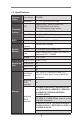
1.2 Speciications Physical Status Processor System Form Factor SSI EEB Dimension 12'' x 13'' (30.5 cm x 33.0 cm) CPU Supports Intel® Xeon processor E51600*/2600/4600 & v2 series * E5-1600 support single socket. Socket Dual Socket R (LGA2011) Power Phase 5 +1 Power Phase Design BIOS System Memory Chipset Intel® C602 BIOS type 64Mb AMI UEFI Legal BIOS Max.
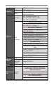
Graphics Controller ASPEED AST2300 VRAM DDR3 16MB Output Supports D-Sub with max.
EP2C602-2TS6/D16 / EP2C602-2T/D16 / EP2C602-2L+/D16 / EP2C602-S6/D16 0 Lan port (RJ45) EP2C602-2T2OS6/D16 / EP2C6022L+2OS6/D16 / EP2C602-2L+OS6/D16 / EP2C602-2TS6/D16 / EP2C602-2T/D16 / EP2C602-2L+O/D16 / EP2C602-2L+/D16 / EP2C602-O/D16 / EP2C602-S6/D16 2 + 1 (for IPMI) PS/2 KB/ mouse NA VGA port D-sub x 1 USB port 4 x USB 2.
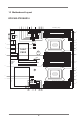
1.3 Motherboard Layout EP2C602-2T2OS6/D16 1 2 3 4 5 6 9 10 11 12 13 14 8 7 33.0cm (13 in) USB 2.0 T: USB1 B: USB2 DDR3_E1 (64 bit, 240-pin module) ATXPWR1 15 DDR3_E2 (64 bit, 240-pin module) COM2 12V_SW1 IPMB_1 1 1 DDR3_F1 (64 bit, 240-pin module) PLED PWRBTN VGA1 COM1 30.5cm (12 in) 1 1 BMC ROM 1 HDLED RESET PSU_SMB1 PANEL1 DDR3_F2 (64 bit, 240-pin module) 1 1 TPM1 AUX_PANEL1 1 1 TR1 NMI_BTN1 1 ME_RECOVERY1 1 ATX12V_1 FRONT_LED_LAN34 USB 2.
1 Dr.
30 USB 2.0 Header (USB_5_6) 31 USB 2.
EP2C602-2TS6/D16 1 2 3 4 5 6 9 10 11 12 13 14 8 7 33.0cm (13 in) USB 2.0 T: USB1 B: USB2 DDR3_E1 (64 bit, 240-pin module) ATXPWR1 15 DDR3_E2 (64 bit, 240-pin module) COM2 12V_SW1 IPMB_1 1 1 DDR3_F1 (64 bit, 240-pin module) PLED PWRBTN VGA1 COM1 30.5cm (12 in) 1 1 BMC ROM 1 HDLED RESET PSU_SMB1 PANEL1 DDR3_F2 (64 bit, 240-pin module) 1 1 TPM1 AUX_PANEL1 1 1 TR1 NMI_BTN1 1 ME_RECOVERY1 1 ATX12V_1 FRONT_LED_LAN34 USB 2.
1 Dr.
30 USB 2.0 Header (USB_5_6) 31 USB 2.
EP2C602-2L+2OS6/D16 1 2 3 4 5 6 9 10 11 12 13 14 8 7 33.0cm (13 in) USB 2.0 T: USB1 B: USB2 DDR3_E1 (64 bit, 240-pin module) ATXPWR1 15 DDR3_E2 (64 bit, 240-pin module) COM2 12V_SW1 IPMB_1 1 1 DDR3_F1 (64 bit, 240-pin module) PLED PWRBTN VGA1 COM1 30.5cm (12 in) 1 1 BMC ROM 1 HDLED RESET PSU_SMB1 PANEL1 DDR3_F2 (64 bit, 240-pin module) 1 1 TPM1 AUX_PANEL1 1 1 TR1 NMI_BTN1 1 ME_RECOVERY1 1 ATX12V_1 FRONT_LED_LAN34 USB 2.
1 Dr.
30 USB 2.0 Header (USB_5_6) 31 USB 2.
EP2C602-2L+OS6/D16 1 2 3 4 5 6 9 10 11 12 13 14 8 7 33.0cm (13 in) USB 2.0 T: USB1 B: USB2 DDR3_E1 (64 bit, 240-pin module) ATXPWR1 15 DDR3_E2 (64 bit, 240-pin module) COM2 12V_SW1 IPMB_1 1 1 DDR3_F1 (64 bit, 240-pin module) PLED PWRBTN VGA1 COM1 30.5cm (12 in) 1 1 BMC ROM 1 HDLED RESET PSU_SMB1 PANEL1 DDR3_F2 (64 bit, 240-pin module) 1 1 TPM1 AUX_PANEL1 1 1 TR1 NMI_BTN1 1 ME_RECOVERY1 1 ATX12V_1 FRONT_LED_LAN34 USB 2.
1 Dr.
30 USB 2.0 Header (USB_5_6) 31 USB 2.
EP2C602-2OS6/D16 1 2 3 4 5 6 9 10 11 12 13 14 8 7 33.0cm (13 in) USB 2.0 T: USB1 B: USB2 DDR3_E1 (64 bit, 240-pin module) ATXPWR1 15 DDR3_E2 (64 bit, 240-pin module) COM2 12V_SW1 IPMB_1 1 1 DDR3_F1 (64 bit, 240-pin module) PLED PWRBTN VGA1 COM1 30.5cm (12 in) 1 1 BMC ROM 1 HDLED RESET PSU_SMB1 PANEL1 DDR3_F2 (64 bit, 240-pin module) 1 1 TPM1 AUX_PANEL1 1 1 TR1 NMI_BTN1 1 ME_RECOVERY1 1 ATX12V_1 FRONT_LED_LAN34 USB 2.
1 Dr.
30 USB 2.0 Header (USB_5_6) 31 USB 2.
EP2C602-2T/D16 1 2 3 4 5 6 9 10 11 12 13 14 8 7 33.0cm (13 in) USB 2.0 T: USB1 B: USB2 DDR3_E1 (64 bit, 240-pin module) ATXPWR1 15 DDR3_E2 (64 bit, 240-pin module) COM2 12V_SW1 IPMB_1 1 1 DDR3_F1 (64 bit, 240-pin module) PLED PWRBTN VGA1 COM1 30.5cm (12 in) 1 1 BMC ROM 1 HDLED RESET PSU_SMB1 PANEL1 DDR3_F2 (64 bit, 240-pin module) 1 1 TPM1 AUX_PANEL1 1 1 TR1 NMI_BTN1 1 ME_RECOVERY1 1 ATX12V_1 FRONT_LED_LAN34 USB 2.
1 Dr.
30 USB 2.0 Header (USB_5_6) 31 USB 2.
EP2C602-2O/D16 1 2 3 4 5 6 9 10 11 12 13 14 8 7 33.0cm (13 in) USB 2.0 T: USB1 B: USB2 DDR3_E1 (64 bit, 240-pin module) ATXPWR1 15 DDR3_E2 (64 bit, 240-pin module) COM2 12V_SW1 IPMB_1 1 1 DDR3_F1 (64 bit, 240-pin module) PLED PWRBTN VGA1 COM1 30.5cm (12 in) 1 1 BMC ROM 1 HDLED RESET PSU_SMB1 PANEL1 DDR3_F2 (64 bit, 240-pin module) 1 1 TPM1 AUX_PANEL1 1 1 TR1 NMI_BTN1 1 ME_RECOVERY1 1 ATX12V_1 FRONT_LED_LAN34 USB 2.
1 Dr.
30 USB 2.0 Header (USB_5_6) 31 USB 2.
EP2C602-O/D16 1 2 3 4 5 6 9 10 11 12 13 14 8 7 33.0cm (13 in) USB 2.0 T: USB1 B: USB2 DDR3_E1 (64 bit, 240-pin module) ATXPWR1 15 DDR3_E2 (64 bit, 240-pin module) COM2 12V_SW1 IPMB_1 1 1 DDR3_F1 (64 bit, 240-pin module) PLED PWRBTN VGA1 COM1 30.5cm (12 in) 1 1 BMC ROM 1 HDLED RESET PSU_SMB1 PANEL1 DDR3_F2 (64 bit, 240-pin module) 1 1 TPM1 AUX_PANEL1 1 1 TR1 NMI_BTN1 1 ME_RECOVERY1 1 ATX12V_1 FRONT_LED_LAN34 USB 2.
1 Dr.
30 USB 2.0 Header (USB_5_6) 31 USB 2.
EP2C602-2L+O/D16 1 2 3 4 5 6 9 10 11 12 13 14 8 7 33.0cm (13 in) USB 2.0 T: USB1 B: USB2 DDR3_E1 (64 bit, 240-pin module) ATXPWR1 15 DDR3_E2 (64 bit, 240-pin module) COM2 12V_SW1 IPMB_1 1 1 DDR3_F1 (64 bit, 240-pin module) PLED PWRBTN VGA1 COM1 30.5cm (12 in) 1 1 BMC ROM 1 HDLED RESET PSU_SMB1 PANEL1 DDR3_F2 (64 bit, 240-pin module) 1 1 TPM1 AUX_PANEL1 1 1 TR1 NMI_BTN1 1 ME_RECOVERY1 1 ATX12V_1 FRONT_LED_LAN34 USB 2.
1 Dr.
30 USB 2.0 Header (USB_5_6) 31 USB 2.
EP2C602-2L+/D16 1 2 3 4 5 6 9 10 11 12 13 14 8 7 33.0cm (13 in) USB 2.0 T: USB1 B: USB2 DDR3_E1 (64 bit, 240-pin module) ATXPWR1 15 DDR3_E2 (64 bit, 240-pin module) COM2 12V_SW1 IPMB_1 1 1 DDR3_F1 (64 bit, 240-pin module) PLED PWRBTN VGA1 COM1 30.5cm (12 in) 1 1 BMC ROM 1 HDLED RESET PSU_SMB1 PANEL1 DDR3_F2 (64 bit, 240-pin module) 1 1 TPM1 AUX_PANEL1 1 1 TR1 NMI_BTN1 1 ME_RECOVERY1 1 ATX12V_1 FRONT_LED_LAN34 USB 2.
1 Dr.
30 USB 2.0 Header (USB_5_6) 31 USB 2.
EP2C602-S6/D16 1 2 3 4 5 6 9 10 11 12 13 14 8 7 33.0cm (13 in) USB 2.0 T: USB1 B: USB2 DDR3_E1 (64 bit, 240-pin module) ATXPWR1 15 DDR3_E2 (64 bit, 240-pin module) COM2 12V_SW1 IPMB_1 1 1 DDR3_F1 (64 bit, 240-pin module) PLED PWRBTN VGA1 COM1 30.5cm (12 in) 1 1 BMC ROM 1 HDLED RESET PSU_SMB1 PANEL1 DDR3_F2 (64 bit, 240-pin module) 1 1 TPM1 AUX_PANEL1 1 1 TR1 NMI_BTN1 1 ME_RECOVERY1 1 ATX12V_1 FRONT_LED_LAN34 USB 2.
1 Dr.
30 USB 2.0 Header (USB_5_6) 31 USB 2.
1.4 I/O Panel EP2C602-2T2OS6/D16 1 9 1 2 3 4 5 2 8 7 Serial Port (COM1) Management LAN Port (MNG_LAN)* 10G SFP+ LAN Port (LAN4)** 10G SFP+ LAN Port (LAN3)** 10G LAN Port (LAN2) 5 6 6 7 8 9 3 4 10G LAN Port (LAN1) USB 2.0 Ports (USB_3_4) D-Sub Port (VGA1) USB 2.0 Ports (USB_1_2) * There are two LEDs on each LAN port. Please refer to the table below for the LAN port LED indications.
EP2C602-2TS6/D16 2 1 7 1 2 3 4 5 6 Serial Port (COM1) Management LAN Port (MNG_LAN)* 10G LAN Port (LAN2) 10G LAN Port (LAN1) 4 3 5 USB 2.0 Ports (USB_3_4) 6 D-Sub Port (VGA1) 7 USB 2.0 Ports (USB_1_2) * There are two LEDs on each LAN port. Please refer to the table below for the LAN port LED indications.
EP2C602-2L+2OS6/D16 1 9 1 2 3 4 5 2 8 7 Serial Port (COM1) Management LAN Port (MNG_LAN)* 10G SFP+ LAN Port (LAN4)** 10G SFP+ LAN Port (LAN3)** 1G LAN Port (LAN2) 5 6 6 7 8 9 3 4 1G LAN Port (LAN1) USB 2.0 Ports (USB_3_4) D-Sub Port (VGA1) USB 2.0 Ports (USB_1_2) * There are two LEDs on each LAN port. Please refer to the table below for the LAN port LED indications.
EP2C602-2L+OS6/D16 2 1 8 1 2 3 4 5 7 6 Serial Port (COM1) Management LAN Port (MNG_LAN)* 10G SFP+ LAN Port (LAN3)** 1G LAN Port (LAN2) 1G LAN Port (LAN1) 5 4 3 6 USB 2.0 Ports (USB_3_4) 7 D-Sub Port (VGA1) 8 USB 2.0 Ports (USB_1_2) * There are two LEDs on each LAN port. Please refer to the table below for the LAN port LED indications.
EP2C602-2OS6/D16 1 7 1 2 3 4 2 5 6 Serial Port (COM1) Management LAN Port (MNG_LAN)* 10G SFP+ LAN Port (LAN4)** 10G SFP+ LAN Port (LAN3)** 3 4 5 USB 2.0 Ports (USB_3_4) 6 D-Sub Port (VGA1) 7 USB 2.0 Ports (USB_1_2) * There are two LEDs on each LAN port. Please refer to the table below for the LAN port LED indications.
EP2C602-2T/D16 2 1 7 1 2 3 4 5 6 Serial Port (COM1) Management LAN Port (MNG_LAN)* 10G LAN Port (LAN2) 10G LAN Port (LAN1) 4 3 5 USB 2.0 Ports (USB_3_4) 6 D-Sub Port (VGA1) 7 USB 2.0 Ports (USB_1_2) * There are two LEDs on each LAN port. Please refer to the table below for the LAN port LED indications.
EP2C602-2O/D16 1 7 1 2 3 4 2 5 6 Serial Port (COM1) Management LAN Port (MNG_LAN)* 10G SFP+ LAN Port (LAN4)** 10G SFP+ LAN Port (LAN3)** 3 4 5 USB 2.0 Ports (USB_3_4) 6 D-Sub Port (VGA1) 7 USB 2.0 Ports (USB_1_2) * There are two LEDs on each LAN port. Please refer to the table below for the LAN port LED indications.
EP2C602-O/D16 2 1 6 4 5 1 Serial Port (COM1) 2 Management LAN Port (MNG_LAN)* 3 10G SFP+ LAN Port (LAN3)** 3 4 USB 2.0 Ports (USB_3_4) 5 D-Sub Port (VGA1) 6 USB 2.0 Ports (USB_1_2) * There are two LEDs on each LAN port. Please refer to the table below for the LAN port LED indications.
EP2C602-2L+O/D16 2 1 8 1 2 3 4 5 7 6 Serial Port (COM1) Management LAN Port (MNG_LAN)* 10G SFP+ LAN Port (LAN3)** 1G LAN Port (LAN2) 1G LAN Port (LAN1) 5 4 3 6 USB 2.0 Ports (USB_3_4) 7 D-Sub Port (VGA1) 8 USB 2.0 Ports (USB_1_2) * There are two LEDs on each LAN port. Please refer to the table below for the LAN port LED indications.
EP2C602-2L+/D16 2 1 7 1 2 3 4 5 6 Serial Port (COM1) Management LAN Port (MNG_LAN)* 1G LAN Port (LAN2) 1G LAN Port (LAN1) 4 3 5 USB 2.0 Ports (USB_3_4) 6 D-Sub Port (VGA1) 7 USB 2.0 Ports (USB_1_2) * There are two LEDs on each LAN port. Please refer to the table below for the LAN port LED indications.
EP2C602-S6/D16 2 1 7 1 2 3 4 5 6 Serial Port (COM1) Management LAN Port (MNG_LAN)* 1G LAN Port (LAN2) 1G LAN Port (LAN1) 4 3 5 USB 2.0 Ports (USB_3_4) 6 D-Sub Port (VGA1) 7 USB 2.0 Ports (USB_1_2) * There are two LEDs on each LAN port. Please refer to the table below for the LAN port LED indications.
EES4!21770244402711 EES4!21770244402711 Rvbe.Diboofm!Nfnpsz!y9!Tmput DI!B DI!B DI!C DI!C Joufm!Qspdfttps DI!D EES4!21770244402711 DI!E EES4!21770244402711 Sandy Bridge-E Joufm!Qspdfttps RQJ Sandy Bridge-E MHB.3122!Qjo!Tpdlfu DQV3 MHB.3122!Qjo!Tpdlfu DQV2 DI!D DI!E EES4!21770244402711 EES4!21770244402711 EES4!21770244402711 EES4!21770244402711 Q DJF 936::!Y9 QDJF MTJ!3419!Y9 QDJF Y6510J461.CU3!!Y9 QDJ.F!4!Y27!TMPU!!QDJF8 ENJ 53 TBUB!CVT Ijhi.
Chapter 2: Installation Before you install the motherboard, study the coniguration of your chassis to ensure that the motherboard its into it. EP2C602 Series are dual socket motherboards that support Intel® Xeon® E5-2400/1400 Series Processors. Please install a primary processor (BootStrap Processor) into “CPU_BSP1” socket and then install a nonPrimary Processor (Application Processors) into “CPU_AP1” socket. *For a single CPU, please install it into “CPU_BSP1” socket (framed by a square). 2.
2.3 CPU Installation Load Lever For the installation of Intel 2011-Pin CPU, please follow the steps below. Load Lever Contact Array Socket Body Load Plate 2011-Pin Socket Overview Before you insert the 2011-Pin CPU into the socket, please check if the CPU surface is unclean or if there are any bent pins in the socket. Do not force to insert the CPU into the socket if above situation is found. Otherwise, the CPU will be seriously damaged. Step 1. Open the socket: Step 1-1.
Step 2-2. Locate Pin1 and the two orientation key notches. alignment key orientation key notch Pin1 alignment key orientation key notch 2011-Pin CPU 2011-Pin Socket For proper inserting, please ensure to match the four orientation key notches of the CPU with the four alignment keys of the socket. Step 2-3. Carefully place the CPU into the socket by using a purely vertical motion. Step 2-4. Verify that the CPU is within the socket and properly mated to the orient keys. Step 3.
2.4 Installation of CPU Fan and Heatsink This motherboard is equipped with 2011-Pin socket that supports Intel 2011-Pin CPU. Please adopt the type of heatsink and cooling fan compliant with Intel 2011Pin CPU to dissipate heat. Before you installed the heatsink, you need to spray thermal interface material between the CPU and the heatsink to improve heat dissipation. Ensure that the CPU and the heatsink are securely fastened and in good contact with each other.
2.5 Installation of Memory Modules (DIMM) This motherboard provides four 240-pin DDR3 (Double Data Rate 3) DIMM slots, and supports Dual Channel Memory Technology. For dual channel configuration, you always need to install two identical (the same brand, speed, size and chip-type) memory modules in the DDR3 DIMM slots to activate Dual Channel Memory Technology. Otherwise, it will operate at single channel mode. 1. 2. 3. 4. 5.
Installing a DIMM Please make sure to disconnect the power supply before adding or removing DIMMs or system components. Step 1. Unlock a DIMM slot by pressing the retaining clips outward. Step 2. Align a DIMM on the slot such that the notch on the DIMM matches the break on the slot. The DIMM only its in one correct orientation. It will cause permanent damage to the motherboard and the DIMM if you force the DIMM into the slot at incorrect orientation. Step 3.
2.6 Expansion Slots (PCI Express Slots) There are 2 PCI Express slots on the motherboard. PCIE slots: PCIE6 and PCIE7 (PCIE 3.0 x16 slot) are used for PCI Express x16 lane width graphics cards. Please note that PCIE6 is available ONLY when the irst CPU (CPU_BSP1) is installed, and PCIE7 is available ONLY when the second CPU (CPU_AP1) is installed. Installing an expansion card Step 1. Step 2. Step 3. Step 4. Step 5. Step 6.
2.7 Jumpers Setup The illustration shows how jumpers are setup. When the jumper cap is placed on pins, the jumper is “Short”. If no jumper cap is placed on pins, the jumper is “Open”. The illustration shows a 3-pin jumper whose pin1 and pin2 are “Short” when jumper cap is placed on these 2 pins.
2.8 Onboard Headers and Connectors Onboard headers and connectors are NOT jumpers. Do NOT place jumper caps over these headers and connectors.
SCU Connector This SCU connector supports SAS/SATA data cables for internal storage devices. The current SAS2/SATA3 interface allows up to 6.0 Gb/s data transfer rate. For connecting SAS HDDs, please contact SAS data cable dealers. (SCU_PORT_0) SCU_PORT_0 USB 2.
Connect the power switch, reset switch and system status indicator on the chassis to this header according to the pin assignments below. Note the positive and negative pins before connecting the cables. PWRBTN (Power Switch): Connect to the power switch on the chassis front panel. You may conigure the way to turn off your system using the power switch. RESET (Reset Switch): Connect to the reset switch on the chassis front panel.
A. Front panel SMBus connecting pin (6-pin FPSMB) This header allows you to connect SMBus (System Management Bus) equipment. It can be used for communication between peripheral equipment in the system, which has slower transmission rates, and power management equipment. B. Internet status indicator (2-pin LAN1_LED, LAN2_LED) These two 2-pin headers allow you to use the Gigabit internet indicator cable to connect to the LAN status indicator.
Though this motherboard provides a 4-Pin CPU fan (Quiet Fan) connector, 3-Pin CPU fans can still work successfully even without the fan speed control function. If you plan to connect a 3-Pin CPU fan to the CPU fan connector on this motherboard, please connect it to Pin 1-3. Pin 1-3 Connected 3-Pin Fan Installation ATX Power Connector 24 13 12 1 (24-pin ATXPWR1) Please connect an ATX power supply to this connector.
Serial port Header This COM2 header supports a serial port module. (9-pin COM2) Intelligent Platform Management Bus header IPMB_SCL IPMB_SDA (4-pin IPMB_1) GND No connect Thermal Sensor header TR1 (3-pin TR1) TR1 1 GND (5-pin PSU_SMB1) SMBCLK +3VSB ALERT PSU SMBus This 4-pin connector is used to provide a cabled baseboard or front panel connection for value added features and 3rd-party add-in cards, such as Emergency Management cards, that provide management features using the IPMB.
Front Lan LED Connector LAN4_LINK LAN3_ACT 1 (4-pin FRONT_LED_LAN34) LAN3_LINK LAN4_ACT Serial General Purpose Input/Output Header SCLOCK SLOAD GND (7-pin SATA_SGPIO1) This 4-pin connector is used for the front LAN status indicator. This header supports Serial Link interface for onboard SATA connections. 1 SDATAOUT GND This header is used for the SM BUS devices.
2.9 Driver Installation Guide To install the drivers to your system, please insert the support CD to your optical drive irst. Then, the drivers compatible to your system can be autodetected and listed on the support CD driver page. Please follow the order from top to bottom to install those required drivers. Therefore, the drivers you install can work properly.
Chapter 3: UEFI SETUP UTILITY 3.1 Introduction This section explains how to use the UEFI SETUP UTILITY to conigure your system. The UEFI chip on the motherboard stores the UEFI SETUP UTILITY. You may run the UEFI SETUP UTILITY when you start up the computer. Please press or during the Power-On-Self-Test (POST) to enter the UEFI SETUP UTILITY, otherawise, POST will continue with its test routines.
3.1.2 Navigation Keys Use < > key or < > key to choose among the selections on the menu bar, and use < > key or < > key to move the cursor up or down to select items, then press to get into the sub screen. You can also use the mouse to click your required item. Please check the following table for the descriptions of each navigation key.
3.2 Main Screen When you enter the UEFI SETUP UTILITY, the Main screen will appear and display the system overview.
3.3 Advanced Screen In this section, you may set the conigurations for the following items: ACPI Coniguration, Intel(LT-SX) TXT Coniguration, WHEA Coniguration, CPU Configuration, North Bridge Configuration, South Bridge Configuration, USB Coniguration, ME Subsystem, Clock Generator Coniguration, Storage Coniguration,Super IO Coniguration, Serial Port Console Redirection and Voltage Control. Setting wrong values in this section may cause the system to malfunction.
3.3.1 ACPI Coniguration Suspend Mode Use this item to enable or disable the highest ACPI Sleep state (S1). If enabled, the system enters S1 level when the SUSPEND button is pressed. ACPI HPET Table Use this item to enable or disable ACPI HPET Table. The default value is [Enabled]. PCI Devices Power On Use this item to enable or disable PCI devices to turn on the system from the power-soft-off mode. RTC Alarm Power On Use this item to enable or disable RTC (Real Time Clock) to power on the system.
3.3.
3.3.3 WHEA Coniguration WHEA Support Use this option to enable or disable Windows Hardware Error Architecture. The default value is [Enabled].
3.3.4 CPU Coniguration CPU_BSP1 Information Display information regarding the primary processor (BootStrap Processor). CPU_AP1 Information Display information regarding the non-primary processor (Application Processors). Intel Hyper Threading Technology To enable this feature, a computer system with an Intel processor that supports Hyper-Threading technology and an operating system that includes optimization for this technology is required.
No-Execute Memory Protection No-Execution (NX) Memory Protection Technology is an enhancement to the IA-32 Intel Architecture. An IA-32 processor with “No Execute (NX) Memory Protection” can prevent data pages from being used by malicious software to execute codes. This option will be hidden if the current CPU does not support No-Excute Memory Protection. Hardware Prefetcher Use this turn on/off the MLC streamer prefetcher.
3.3.5 North Bridge Coniguration IOH ( I/O hub) Coniguration Intel® VT-d Use this to enable/disable Intel® Virtualization Technology for the Directed I/O. Intel® I/OAT Use this to enable/disable Intel® I/O AccelearationTechnology. Primary Graphics Adapter This allows you to select a graphics device as the primary display. The default value is [PCI Express]. Onboard VGA Enable or disable the onboard VGA. Onboard LAN1 & LAN2 This allows you to enable or disable onboard LAN1 & LAN2.
PCIE7 Link Speed This allows you to select PCIE7 Link Speed. QPI ( Intel Quickpath Interconnect) Coniguration Isoc Use this to enable/disable Isoc. It is recommended to select [En abled]. QPI Link Speed Mode This allows you to select QPI Link Speed Mode. It is recommended to select [Auto]. QPI Link Frequency Select This allows you to select QPI Link Frequency. Memory Coniguration Memory Mode Select the mode for memory initialization. [Independent]: Independent channel mode.
DRAM RAPL (Running Average Power Limit ) Mode RAPL (Running Average Power Limit ) provides mechanisms to enforce power consumption limits on supported processors. The default is [DRAM RAPL Mode 1]. Numa Enable or disable the support of Non-Uniform Memory Access. MPST Support Enable or disable the support of Memory Power StateTable. DRAM Frequency If [Auto] is selected, the motherboard will detect the memory module(s) inserted and assign the appropriate frequency auto matically.
3.3.6 South Bridge Coniguration Restore on AC/Power Loss This allows you to set the power state after an unexpected AC/power loss. If [Power Off] is selected, the AC/power remains off when the power recovers. If [Power On] is selected, the AC/power resumes and the system starts to boot up when the power recovers. Deep Sleep Mobile platforms support Deep S4/S5 in DC only and desktop platforms support Deep S4/S5 in AC only. The default value is [Disabled].
3.3.7 USB Coniguration USB 2.0 Controller Use this item to enable or disable the use of USB 2.0 controller. Legacy USB Support Use this option to select legacy support for USB devices. There are four coniguration options: [Enabled], [Auto], [Disabled] and [UEFI Setup Only]. The default value is [Enabled]. Please refer to below descriptions for the details of these four options: [Enabled] - Enables support for legacy USB. [Auto] - Enables legacy support if USB devices are connected.
3.3.8 Intel® ME Subsystem Intel® ME Subsystem Display information regarding Intel® Management Engine.
3.3.9 Clock Generator Coniguration Spread Spectrum It is recommended to disable this option for better system stability.
3.3.10 Storage Coniguration SATA Mode Selection This item is for SATAIII_0, SATAIII_1 and SATAII_PORT_0 ports. Use this to select SATA mode. Coniguration options: [IDE Mode], [AHCI Mode], [RAID Mode] and [Disabled]. The default value is [AHCI Mode]. AHCI (Advanced Host Controller Interface) supports NCQ and other new features that will improve SATA disk performance but IDE mode does not have these advantages. SATA Aggressive Link Power Management Use this item to conigure Aggressive Link Power Management.
Onboard SCU Oprom/Driver Use this to enable or disable LSI SAS Option ROM. If Option ROM is disabled, you cannot use the SATA devices connected to the LSI SAS controller as Boot Device. We recommend to use Intel® C602 SATA ports (SATAIII_0, SATAIII_1 and SATAII_PORT_0) for your bootable devices. This will minimum your boot time and get the best performance. But if you still want to boot from the LSI SAS controller, you can enable it from the UEFI.
3.3.11 Super IO Coniguration Serial Port 1 Coniguration Use this item to conigure the onboard serial port 1. Serial Port 2 Coniguration Use this item to conigure the onboard serial port 2.
3.3.12 Serial Port Console Redirection Console Redirection Use this option to enable or disable Console Redirection. Console Redirection Settings Use this option to conigure Console Redirection Settings.
3.3.13 Voltage Control DRAM 1 Voltage Use this to select DRAM 1 Voltage. The default value is [Auto]. DRAM 2 Voltage Use this to select DRAM 2 Voltage. The default value is [Auto]. PLL 1 Voltage Use this to select CPU PLL 1 Voltage. The default value is [Auto]. PLL 2 Voltage Use this to select CPU PLL 2 Voltage. The default value is [Auto]. VTT 1 Voltage Use this to select VTT 1 Voltage. The default value is [Auto]. VTT 2 Voltage Use this to select VTT 2 Voltage. The default value is [Auto].
3.4 Hardware Health Event Monitoring Screen In this section, it allows you to monitor the status of the hardware on your system, including the parameters of the CPU temperature, motherboard temperature and the critical voltage. CPU1_FAN Setting This allows you to set the speed of CPU1_FAN. The default value is [Full On]. CPU2_FAN Setting This allows you to set the speed of CPU2_FAN. The default value is [Full On]. REAR_FAN1 Setting This allows you to set the speed of REAR_FAN1.
FRNT_FAN4 Setting This allows you to set the speed of FRNT_FAN4. The default value is [Full On]. Watch Dog Timer This allows you to enable or disable the Watch Dog Timer. The default value is [Disabled]. Case Open Feature This allows you to enable or disable the Case Open Feature. The default value is [Enabled]. Clear Status Enable to clear case open status if case open has been detected.
3.5 Server Management System Event Log Enter to conigure System Event Logging features during boot. BMC Network Coniguration Enter to conigure BMC Network parameters.
3.6 Boot Screen In this section, it will display the available devices on your system for you to conigure the boot settings and the boot priority. Boot Option #1 Select boot option #1. Setup Prompt Timeout This shows the number of seconds to wait for setup activation key. 65535(0XFFFF) means indeinite waiting. Bootup NumLock State If this item is set to [On], it will automatically activate the Numeric Lock function after boot-up. Other PCI Device ROM Priority Use this to adjust the PCI ROM Priority.
Boot From Onboard LAN Use this item to enable or disable the Boot From Onboard LAN feature. Boot From PCIE LAN Use this item to enable or disable the Boot From PCIE LAN feature.
3.7 Security Screen In this section, you may set or change the supervisor/user password for the system. For the user password, you may also clear it.
3.8 Exit Screen Save Changes and Exit When you select this option, the following message “Save coniguration changes and exit setup?” will pop-out. Select [Yes] to save the changes and exit the UEFI SETUP UTILITY. Discard Changes and Exit When you select this option, the following message “Discard changes and exit setup?” will pop-out. Select [Yes] to exit the UEFI SETUP UTILITY without saving any changes. Discard Changes When you select this option, the following message “Discard changes?” will pop-out.
3.9 Event Logs Change Smbios Event Log Settings This allows you to conigure the Smbios Event Log Settings. View Smbois Event Log This allows you to view the Smbios Event Log.
Chapter 4: Software Support 4.1 Install Operating System This motherboard supports Microsoft® Windows® Server 2003 / 2003 R2 / 2008 / 2008 R2 / Linux compliant. Because motherboard settings and hardware options vary, use the setup procedures in this chapter for general reference only. Refer your OS documentation for more information. 4.2 Support CD Information The Support CD that came with the motherboard contains necessary drivers and useful utilities that enhance the motherboard’s features. 4.2.
Chapter 5: Troubleshooting 5.1 Troubleshooting Procedures Follow the procedures below to troubleshoot your system. Always unplug the power cord before adding, removing or changing any hardware components. Failure to do so may cause physical injuries to you and damages to motherboard components. 1. Disconnect the power cable and check whether the PWR LED is off. 2. Unplug all cables, connectors and remove all add-on cards from the motherboard. Make sure that the jumpers are set to default settings. 3.
faulty ones. 5. Check the settings of the 115V/230V switch on the power supply. Unable to save system setup conigurations... 1. Verify if the battery on the motherboard provides ~3VDC. Install a new battery if it does not. 2. Conirm whether your power supply provides adaquate and stable power. Other problems... 1. Try searching keywords related to your problem on ASRock’s FAQ page: http://www.asrock.com/support/faq.asp 2. Try downloading and updating the latest UEFI on ASRock’s website: http://www.asrock.
5.2 Technical Support Procedures If you have tried the troubleshooting procedures mentioned above and the problems are still unsolved, please contact ASRock’s technical support with the following information: 1. Your contact information 2. Model name, BIOS version and problem type. 3. System coniguration. 4. Problem description. You may contact ASRock’s technical support at: http://www.asrock.com/support/tsd.asp 5.