FM2A58M+ BTC User Manual
Version 1.0 Published April 2014 Copyright©2014 ASRock INC. All rights reserved. Copyright Notice: No part of this documentation may be reproduced, transcribed, transmitted, or translated in any language, in any form or by any means, except duplication of documentation by the purchaser for backup purpose, without written consent of ASRock Inc.
Contents 1. Introduction 1 1.1 Package Contents 1 1.2 Specifications 2 1.3 Unique Features 6 1.4 Motherboard Layout 11 1.5 I/O Panel 13 2. Installation 14 2.1 CPU Installation 15 2.2 Installation of CPU Fan and Heatsink 16 2.3 Installation of Memory Modules (DIMM) 17 2.4 Expansion Slots (PCI and PCI Express Slots) 19 2.5 Jumpers Setup 20 2.6 Onboard Headers and Connectors 21 3. Software and Utilities Operation 25 4. UEFI SETUP UTILITY 33 4.1 33 Introduction 4.1.
.4.2 North Bridge Configuration 40 4.4.3 South Bridge Configuration 41 4.4.4 Storage Configuration 42 4.4.5 Super IO Configuration 43 4.4.6 ACPI Configuration 44 4.4.7 USB Configuration 46 4.5 Tool 48 4.6 Hardware Health Event Monitoring Screen 51 4.7 Boot Screen 52 4.8 Security Screen 54 4.
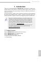
FM2A58M+ BTC 1. Introduction Thank you for purchasing ASRock FM2A58M+ BTC motherboard, a reliable motherboard produced under ASRock’s consistently stringent quality control. It delivers excellent performance with robust design conforming to ASRock’s commitment to quality and endurance. In this documentation, Chapter 1 and 2 contains the introduction of the motherboard and step-by-step installation guides. Chapter 3 contains the operation guide of the software and utilities.
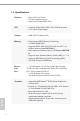
1.2 Specifications Platform • Micro ATX Form Factor • All Solid Capacitor design • High Density Glass Fabric PCB CPU • Supports Socket FM2+ 95W / FM2 100W processors • 4 + 2 Power Phase design Chipset • AMD A58 FCH (Bolton-D2) Memory • Dual Channel DDR3 Memory Technology • 2 x DDR3 DIMM Slots • Supports DDR3 1866/1600/1333/1066 non-ECC, unbuffered memory (see CAUTION 1) • Max. capacity of system memory: 32GB (see CAUTION 2) • Supports Intel ® Extreme Memory Profile (XMP) 1.3 / 1.
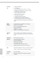
FM2A58M+ BTC • Supports D-Sub with max. resolution up to 1920x1200 @ 60Hz • Supports AMD Steady VideoTM 2.0: New video post processing capability for automatic jitter reduction on home/online video • Supports HDCP with DVI-D Port • Supports Full HD 1080p Blu-ray (BD) playback with DVI-D Port Audio • 5.
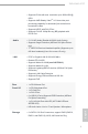
English 4 Connector • • • • • • • • • • • 1 x Print Port Header 1 x TPM Header 2 x CPU Fan Connectors (1 x 4-pin, 1 x 3-pin) 2 x Chassis Fan Connectors (1 x 4-pin, 1 x 3-pin) 1 x Power Fan Connector (3-pin) 1 x 24 pin ATX Power Connector 1 x 8 pin 12V Power Connector 1 x PCIe Power Connector 1 x Front Panel Audio Connector 1 x USB Power Jumper (Ultra USB Power) 2 x USB 2.0 Headers (Support 4 USB 2.
FM2A58M+ BTC * For detailed product information, please visit our website: http://www.asrock.com WARNING Please realize that there is a certain risk involved with overclocking, including adjusting the setting in the BIOS, applying Untied Overclocking Technology, or using third-party overclocking tools. Overclocking may affect your system’s stability, or even cause damage to the components and devices of your system. It should be done at your own risk and expense.
1.3 Unique Features ASRock A-Tuning A-Tuning is ASRock’s multi purpose software suite with a new interface, more new features and improved utilities, including XFast RAM, Dehumidifier, Good Night LED, FAN-Tastic Tuning, OC Tweaker and a whole lot more. ASRock Instant Boot ASRock Instant Boot allows you to turn on your PC in just a few seconds, provides a much more efficient way to save energy, time, money, and improves system running speed for your system.
FM2A58M+ BTC Suspend to RAM (S3), hibernation mode (S4) or power off (S5). With APP Charger driver installed, you can easily enjoy the marvelous charging experience. ASRock XFast LAN ASRock XFast LAN provides a faster internet access, which includes the benefits listed below. LAN Application Prioritization: You can configure your application’s priority ideally and/or add new programs. Lower Latency in Game: After setting online game’s priority higher, it can lower the latency in games.
ASRock Internet Flash ASRock Internet Flash searches for available UEFI firmware updates from our servers. In other words, the system can autodetect the latest UEFI from our servers and flash them without entering Windows® OS. ASRock UEFI System Browser ASRock UEFI system browser is a useful tool included in graphical UEFI. It can detect the devices and configurations that users are currently using in their PC.
FM2A58M+ BTC ASRock Interactive UEFI ASRock Interactive UEFI is a blend of system configuration tools, cool sound effects and stunning visuals. The unprecedented UEFI provides a more attractive interface and brings a lot more amusing. ASRock Fast Boot With ASRock’s exclusive Fast Boot technology, it takes less than 1.5 seconds to logon to Windows® 8 from a cold boot. No more waiting! The speedy boot will completely change your user experience and behavior.
ASRock USB Key In a world where time is money, why waste precious time everyday typing usernames to log in to Windows? Why should we even bother memorizing those foot long passwords? Just plug in the USB Key and let your computer log in to windows automatically! ASRock FAN-Tastic Tuning ASRock FAN-Tastic Tuning is included in A-Tuning. Configure up to five different fan speeds using the graph. The fans will automatically shift to the next speed level when the assigned temperature is met.
FM2A58M+ BTC 1.4 Motherboard Layout 1 2 3 PS2 Mouse CPU_FAN2 CPU_FAN1 ATX12V1 USB01_PWR1 USB 2.0 T: USB0 B: USB1 ATXPWR1 VGA1 SOCKET FM2b DVI1 FM2A58M+ BTC USB 2.0 T: USB0 B: USB1 DDR3_B1 (64 bit, 240-pin module) 1 24 DDR3_A1 (64 bit, 240-pin module) PS2 Keyboard PWR_FAN1 5 4 6 CHA_FAN2 23 LAN RJ-45 LAN USB 2.0 T: USB2 B: USB3 PCIE_PWR1 22 Center: FRONT Top: LINE IN Bottom: MIC IN PCIE1 PCI Express 3.
No.
FM2A58M+ BTC 1.5 I/O Panel 1 11 10 9 8 7 2 3 4 6 5 No. Description No. Description 1 PS/2 Mouse Port (Green) 7 USB 2.0 Ports (USB23) 2 LAN RJ-45 Port* 8 D-Sub Port (VGA1) 3 Line In (Light Blue) 9 DVI-D Port (DVI1) 4 Front Speaker (Lime) 10 USB 2.0 Ports (USB01) 5 Microphone (Pink) 11 PS/2 Keyboard Port (Purple) 6 USB 2.0 Ports (USB45) * There are two LEDs on the LAN port. Please refer to the table below for the LAN port LED indications.
2. Installation This is an ATX form factor motherboard. Before you install the motherboard, study the configuration of your chassis to ensure that the motherboard fits into it. Pre-installation Precautions Take note of the following precautions before you install motherboard components or change any motherboard settings. Before you install or remove any component, ensure that the power is switched off or the power cord is detached from the power supply.
FM2A58M+ BTC 2.1 CPU Installation Step 1. Unlock the socket by lifting the lever up o to a 90 angle. Step 2. Step 3. Position the CPU directly above the socket such that the CPU corner with the golden triangle matches the socket corner with a small triangle. Carefully insert the CPU into the socket until it fits in place. The CPU fits only in one correct orientation. DO NOT force the CPU into the socket to avoid bending of the pins.
2.2 Installation of CPU Fan and Heatsink After you install the CPU into this motherboard, it is necessary to install a larger heatsink and cooling fan to dissipate heat. You also need to spray thermal grease between the CPU and the heatsink to improve heat dissipation. Make sure that the CPU and the heatsink are securely fastened and in good contact with each other. Then connect the CPU fan to the CPU FAN connector (CPU_FAN1 and CPU_FAN2, see Page 11, No. 3 and No. 4).
FM2A58M+ BTC 2.3 Installation of Memory Modules (DIMM) This motherboard provides two 240-pin DDR3 (Double Data Rate 3) DIMM slots, and supports Dual Channel Memory Technology. 1. For dual channel configuration, you always need to install identical (the same brand, speed, size and chip-type) DDR3 DIMM pairs. 2. It is unable to activate Dual Channel Memory Technology with only one memory module installed. 3.
1 2 3 English 18
FM2A58M+ BTC 2.4 Expansion Slots (PCI and PCI Express Slots) There are 4 PCI Express slots on this motherboard. Before installing an expansion card, please make sure that the power supply is switched off or the power cord is unplugged. Please read the documentation of the expansion card and make necessary hardware settings for the card before you start the installation. English PCIE Slots: PCIE1 (PCIe 3.0 x16 slot) is used for PCI Express x16 lane width graphics cards PCIE2 / PCIE3 / PCIE4 (PCIe 2.
2.5 Jumpers Setup The illustration shows how jumpers are setup. When the jumper cap is placed on pins, the jumper is “Short”. If no jumper cap is placed on pins, the jumper is “Open”. The illustration shows a 3-pin jumper whose pin1 and pin2 are “Short” when jumper cap is placed on these 2 pins. Jumper Setting Description Clear CMOS Jumper (CLRCMOS1) (see p.11, No. 8) Default Clear CMOS Note: CLRCMOS1 allows you to clear the data in CMOS.
FM2A58M+ BTC 2.6 Onboard Headers and Connectors Onboard headers and connectors are NOT jumpers. Do NOT place jumper caps over these headers and connectors. Placing jumper caps over the headers and connectors will cause permanent damage of the motherboard! Serial ATA2 Connectors (SATA_1: see p.11, No. 15) SATA_2 SATA_4 SATA_6 SATA_1 SATA_3 SATA_5 (SATA_2: see p.11, No. 16) (SATA_3: see p.11, No. 14) (SATA_4: see p.11, No. 13) (SATA_5: see p.11, No.
E. To activate the front mic. For Windows® 8.1 / 8.1 64-bit / 8 / 8 64-bit / 7 / 7 64-bit / XP / XP 64bit OS: Go to the “FrontMic” Tab in the Realtek Control panel. Adjust “Recording Volume”. System Panel Header PLED+ PLEDPWRBTN# GND (9-pin PANEL1) (see p.11 No. 10) This header accommodates several system front panel functions. 1 GND RESET# GND HDLEDHDLED+ Connect the power switch, reset switch and system status indicator on the chassis to this header according to the pin assignments below.
FM2A58M+ BTC Chassis and Power Fan Connectors (3-pin CHA_FAN1) (see p.11 No. 7) GND +12V CHA_FAN_SPEED FAN_SPEED_CONTROL Please connect the fan cable to the fan connector and match the black wire to the ground pin. (3-pin CHA_FAN2) (see p.11 No. 23) GND + 12V CHA_ FAN_SPEED (3-pin PWR_FAN1) (see p.11 No. 2) CPU Fan Connector FAN_SPEED_CONTROL Please connect the CPU fan CPU_FAN_SPEED (4-pin CPU_FAN1) cable to the connector and +12V (see p.11 No.
Though this motherboard provides 24-pin ATX power connector, it can still work if you adopt a traditional 20-pin ATX power supply. To use the 20-pin ATX power supply, please plug your power supply along with Pin 1 and Pin 13. 20-Pin ATX Power Supply Installation ATX 12V Power Connector (8-pin ATX12V1) (see p.11 No. 1) 1 4 5 8 12 24 1 13 Please connect an ATX 12V power supply to this connector.
FM2A58M+ BTC 3. Software and Utilities Operation 3.1 Installing Drivers The Support CD that comes with the motherboard contains necessary drivers and useful utilities that enhance the motherboard’s features. Running The Support CD To begin using the support CD, insert the CD into your CD-ROM drive. The CD automatically displays the Main Menu if “AUTORUN” is enabled in your computer. If the Main Menu does not appear automatically, locate and double click on the file “ASRSETUP.
3.2 A-Tuning A-Tuning is ASRock’s multi purpose software suite with a new interface, more new features and improved utilities, including XFast RAM, Dehumidifier, Good Night LED, FAN-Tastic Tuning, OC Tweaker and a whole lot more. 3.2.1 Installing A-Tuning When you install the all-in-one driver to your system from ASRock’s support CD, A-Tuning will be auto-installed as well. After the installation, you will find the icon “A-Tuning“ on your desktop.
FM2A58M+ BTC Tools Various tools and utilities. XFast RAM Boost the system’s performance and extend the HDD’s or SDD’s lifespan! Create a hidden partition, then assign which files should be stored in the RAM drive. Fast Boot Fast Boot minimizes your computer's boot time. Please note that Ultra Fast mode is only supported by Windows 8 and the VBIOS must support UEFI GOP if you are using an external graphics card. OMG Schedule the starting and ending hours of Internet access granted to other users.
FAN-Tastic Tuning Configure up to five different fan speeds using the graph. The fans will automatically shift to the next speed level when the assigned temperature is met. Dehumidifier Prevent motherboard damages due to dampness. Enable this function and configure the period of time until the computer powers on, and the duration of the dehumidifying process. OC Tweaker Configurations for overclocking the system. System Info View information about the system.
FM2A58M+ BTC Tech Service English Contact Tech Service.
3.3 Start8 For those Windows 8 users who miss the Start Menu, Start8 is an ideal solution that brings back the familiar Start Menu along with added customizations for greater efficiency. 3.3.1 Installing Start8 Install Start8, which is located in the folder at the following path of the Support CD: \ ASRock Utility > Start8. 3.3.2 Configuring Start8 Style Select between the Windows 7 style and Windows 8 style Start Menu. Then select the theme of the Start Menu and customize the style of the Start icon.
FM2A58M+ BTC Configure Configure provides configuration options, including icon sizes, which shortcuts you want Start Menu to display, quick access to recently used apps, the functionality of the power button, and more.
Control lets you configure what a click on the start button or a press on the Windows key does. Desktop Desktop allows you to disable the hot corners when you are working on the desktop. It also lets you choose whether or not the system boots directly into desktop mode and bypass the Metro user interface. About Displays information about Start8.
FM2A58M+ BTC 4. UEFI SETUP UTILITY 4.1 Introduction ASRock Interactive UEFI is a blend of system configuration tools, cool sound effects and stunning visuals. Not only will it make BIOS setup less difficult but also a lot more amusing. This section explains how to use the UEFI SETUP UTILITY to configure your system. The UEFI chip on the motherboard stores the UEFI SETUP UTILITY. You may run the UEFI SETUP UTILITY when you start up the computer.
4.1.2 Navigation Keys Please check the following table for the function description of each navigation key.
FM2A58M+ BTC 4.3 OC Tweaker Screen In the OC Tweaker screen, you can set up overclocking features. EZ OC Mode You can use this option to adjust EZ overclocking setting. Please note that overclocing may cause damage to your components and motherboard. It should be done at your own risk and expense. CPU Configuration Overclock Mode Use this to select Overclock Mode. Configuration options: [Auto] and [Manual]. The default value is [Auto].
Multiplier/Voltage Change This item is set to [Auto] by default. If it is set to [Manual], you may adjust the value of Processor Frequency and Processor Voltage. However, it is recommended to keep the default value for system stability. CPU Load-line Calibration CPU Load-line Calibration helps prevent APU voltage droop when the system is under heavy load. NB Load-line Calibration NB Load-line Calibration helps prevent NB voltage droop when the system is under heavy load.
FM2A58M+ BTC DRAM Timing Control DRAM Slot Use this item to view SPD data. DRAM Timing Control Use this item to control DRAM timing. Power Down Enable Use this item to enable or disable DDR power down mode. Bank Interleaving Interleaving allows memory accesses to be spread out over banks on the same node, or accross nodes, decreasing access contention. Channel Interleaving It allows you to enable Channel Memory Interleaving. Configuration options: [Disabled], [Auto]. The default value is [Auto].
4.4 Advanced Screen In this section, you may set the configurations for the following items: CPU Configuration, Nouth Bridge Configuration, South Bridge Configuration, Storage Configuration, Super IO Configuration, ACPI Configuration, USB Configuration and Trusted Computing. Setting wrong values in this section may cause the system to malfunction.
FM2A58M+ BTC 4.4.1 CPU Configuration English Core C6 Mode Use this item to enable or disable Core C6 mode. The default value is [Enabled]. Target TDP Use this item to set the target TDP (Thermal Design Power ). Cool ‘n’ Quiet Use this item to enable or disable AMD’s Cool ‘n’ QuietTM technology. The default value is [Enabled]. Configuration options: [Enabled] and [Disabled]. If you install Windows® 8.1 / 8 / 7 and want to enable this function, please set this item to [Enabled].
4.4.2 North Bridge Configuration IOMMU This allows you to enable or disable IOMMU support. Primary Graphics Adapter This item will switch the PCI Bus scanning order while searching for video card. It allows you to select the type of Primary VGA in case of multiple video controllers. The default value of this feature is [PCI Express]. Configuration options: [Onboard], [PCI] and [PCI Express]. Onboard Graphics Select Enable/Disable/Auto for the onboard graphics.
FM2A58M+ BTC 4.4.3 South Bridge Configuration English Onboard HD Audio Select [Auto], [Enabled] or [Disabled] for the onboard HD Audio feature. If you select [Auto], the onboard HD Audio will be disabled when PCI Sound Card is plugged. Front Panel Select [Auto] or [Disabled] for the onboard HD Audio Front Panel. Onboard LAN This allows you to enable or disable the onboard LAN feature. Good Night LED Enable this option to turn off Power LED when the system is power on.
4.4.4 Storage Configuration SATA Controller Use this item to enable or disable the “SATA Controller” feature. SATA Mode Use this item to adjust SATA Mode. The default value of this option is [AHCI Mode]. Configuration options: [AHCI Mode], [RAID Mode] and [IDE Mode]. If you set this item to RAID mode, it is suggested to install SATA ODD driver on SATA_5 and SATA_6 ports. AMD AHCI BIOS ROM Use this item to enable or disable AMD AHCI BIOS ROM. The default value of this option is [Disabled].
FM2A58M+ BTC 4.4.5 Super IO Configuration English Parallel Port Enable or disable the Parallel port. Device Mode Select the device mode according to your connected device. Change Settings Select the address of the Parallel port.
4.4.6 ACPI Configuration English Suspend to RAM Use this item to select whether to auto-detect or disable the Suspend-toRAM feature. Select [Auto] will enable this feature if the OS supports it. Check Ready Bit Enable to enter the operating system after S3 only when the hard disk is ready, this is recommended for better system stability. Deep Sleep Configure deep sleep mode for power saving when the computer is shut down. We recommend disabling Deep Sleep for better system compatibility and stability.
FM2A58M+ BTC USB Keyboard/Remote Power On Use this item to enable or disable USB Keyboard/Remote to power on the system. USB Mouse Power On Use this item to enable or disable USB Mouse to power on the system. English ACPI HPET table Use this item to enable or disable ACPI HPET Table. The default value is [Enabled]. Please set this option to [Enabled] if you plan to use this motherboard to submit Windows® certification.
4.4.7 USB Configuration USB Controller Use this item to enable or disable the use of USB controller. Legacy USB Support Use this option to select legacy support for USB devices. There are four confi guration options: [Enabled], [Auto], [Disabled] and [UEFI Setup Only]. The default value is [Enabled]. Please refer to below descriptions for the details of these four options: [Enabled] - Enables support for legacy USB. [Auto] - Enables legacy support if USB devices are connected.
FM2A58M+ BTC 4.4.8 Trusted Computing Security Device Support English Enable or disable BIOS support for security device.
4.5 Tool System Browser System Browser can let you easily check your current system configuration in UEFI setup. OMG(Online Management Guard) Administrators are able to establish an internet curfew or restrict internet access at specified times via OMG. You may schedule the starting and ending hours of internet access granted to other users. In order to prevent users from bypassing OMG, guest accounts without permission to modify the system time are required.
FM2A58M+ BTC UEFI Update Utility Instant Flash Instant Flash is a UEFI flash utility embedded in Flash ROM. This convenient UEFI update tool allows you to update system UEFI without entering operating systems first like MS-DOS or Windows®. Just save the new UEFI file to your USB flash drive, floppy disk or hard drive and launch this tool, then you can update your UEFI only in a few clicks without preparing an additional floppy diskette or other complicated flash utility.
Dehumidifier Function Users may prevent motherboard damages due to dampness by enabling “Dehumidifier Function”. When enabling Dehumidifier Function, the computer will power on automatically to dehumidify the system after entering S4/S5 state. Dehumidifier Period This allows users to configure the period of time until the computer powers on and enables “Dehumidifier” after entering S4/S5 state.
FM2A58M+ BTC 4.6 Hardware Health Event Monitoring Screen In this section, it allows you to monitor the status of the hardware on your system, including the parameters of the CPU temperature, motherboard temperature, CPU fan speed, chassis fan speed, and the critical voltage. English CPU Fan 1 & 2 Setting This allows you to set the CPU fan 1 & 2 speed. Confi guration options: [Full On] and [Automatic Mode]. The default is value [Full On].
4.7 Boot Screen In this section, it will display the available devices on your system for you to configure the boot settings and the boot priority. Fast Boot Fast Boot minimizes your computer’s boot time. There are three configuration options: [Disabled], [Fast] and [Ultra Fast]. The default value is [Disabled]. Please refer to below descriptions for the details of these three options: [Disabled] - Disable Fast Boot. [Fast] - The only restriction is you may not boot by using an USB flash drive.
FM2A58M+ BTC Option ROM Messages [Force BIOS] - The third-party ROM messages will be forced to display during the bootsequence. [Keep Current] - The third-party ROM messages will be displayed only if the third-partymanufacturer had set the add-on device to do so. Boot Failure Guard Enable or disable the feature of Boot Failure Guard. Boot Failure Guard Count Enable or disable the feature of Boot Failure Guard Count.
4.8 Security Screen In this section, you may set or change the supervisor/user password for the system. For the user password, you may also clear it. Secure Boot Enable to support Windows® 8 Secure Boot.
FM2A58M+ BTC 4.9 Exit Screen Save Changes and Exit When you select this option, it will pop-out the following message, “Save configuration changes and exit setup?” Select [OK] to save the changes and exit the UEFI SETUP UTILITY. Discard Changes and Exit When you select this option, it will pop-out the following message, “Discard changes and exit setup?” Select [OK] to exit the UEFI SETUP UTILITY without saving any changes.
Contact Information If you need to contact ASRock or want to know more about ASRock, you’re welcome to visit ASRock’s website at http://www.asrock.com; or you may contact your dealer for further information. For technical questions, please submit a support request form at http://www.asrock.com/support/tsd.asp ASRock Incorporation 2F., No.37, Sec. 2, Jhongyang S. Rd., Beitou District, Taipei City 112, Taiwan (R.O.C.) ASRock EUROPE B.V.