H55M-GE User Manual Version 1.0 Published May 2010 Copyright©2010 ASRock INC. All rights reserved.
Copyright Notice: No part of this manual may be reproduced, transcribed, transmitted, or translated in any language, in any form or by any means, except duplication of documentation by the purchaser for backup purpose, without written consent of ASRock Inc. Products and corporate names appearing in this manual may or may not be registered trademarks or copyrights of their respective companies, and are used only for identification or explanation and to the owners’ benefit, without intent to infringe.
Contents 1 Introduction ................................................... 5 1.1 1.2 1.3 1.4 Package Contents .......................................................... Specifications ................................................................ Motherboard Layout ...................................................... I/O Panel ......................................................................... 5 6 11 12 2 Installation ...................................................... 13 2.1 2.2 2.3 2.4 2.
3.5 3.6 3.7 3.8 3.4.5 PCIPnP Configuration ........................................... 3.4.6 Super IO Configuration ........................................ 3.4.7 USB Configuration ............................................... Hardware Health Event Monitoring Screen .................. Boot Screen ................................................................... 3.6.1 Boot Settings Configuration .................................. Security Screen ..........................................................
Chapter 1: Introduction Thank you for purchasing ASRock H55M-GE motherboard, a reliable motherboard produced under ASRock’s consistently stringent quality control. It delivers excellent performance with robust design conforming to ASRock’s commitment to quality and endurance. In this manual, chapter 1 and 2 contain introduction of the motherboard and step-by-step guide to the hardware installation. Chapter 3 and 4 contain the configuration guide to BIOS setup and information of the Support CD.
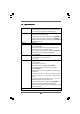
1.2 Specifications Platform CPU Chipset Memory Expansion Slot Graphics * Audio - Micro ATX Form Factor: 9.6-in x 8.7-in, 24.4 cm x 22.1 cm - All Solid Capacitor design (100% Japan-made high-quality Conductive Polymer Capacitors) (H55M-GE R2.
LAN Rear Panel I/O Connector BIOS Feature Support CD Unique Feature - PCIE x1 Gigabit LAN 10/100/1000 Mb/s - Realtek RTL8111E - Supports Wake-On-LAN - Supports LAN Cable Detection I/O Panel - 1 x PS/2 Keyboard Port - 1 x VGA/D-Sub Port - 1 x VGA/DVI-D Port - 1 x HDMI Port - 6 x Ready-to-Use USB 2.0 Ports - 1 x RJ-45 LAN Port with LED (ACT/LINK LED and SPEED LED) - HD Audio Jack: Line in/Front Speaker/Microphone - 6 x SATAII 3.
Hardware Monitor OS Certifications - ASRock OC DNA (see CAUTION 15) - Hybrid Booster: - CPU Frequency Stepless Control (see CAUTION 16) - ASRock U-COP (see CAUTION 17) - Boot Failure Guard (B.F.G.) - Combo Cooler Option (C.C.O.
CAUTION! 1. Intel® CoreTM i3 and Pentium ® G6950 processors do not support Intel® Turbo Boost Technology. 2. 3. About the setting of “Hyper Threading Technology”, please check page 38. This motherboard supports Untied Overclocking Technology. Please read 4. “Untied Overclocking Technology” on page 30 for details. This motherboard supports Dual Channel Memory Technology.
14. ASRock Instant Flash is a BIOS flash utility embedded in Flash ROM. This convenient BIOS update tool allows you to update system BIOS without entering operating systems first like MS-DOS or Windows®. With this utility, you can press key during the POST or press key to BIOS setup menu to access ASRock Instant Flash.
1.3 Motherboard Layout 1 3 2 6 5 4 7 8 22.1cm (8.7 in) PS2_USB_PWR1 PS2 Keyboard 1 USB 2.0 T: USB4 B: USB5 1 USB_PWR2 CPU_FAN1 PWR_FAN1 DDR3_B1 (64 bit, 240-pin module) ATXPWR1 9 H55M-GE DDR3 2600+ PCI Express 2.0 HD_AUDIO1 CHA_FAN1 Center: FRONT Top: LINE IN Bottom: MIC IN LAN PHY 1 35 DDR3_B2 (64 bit, 240-pin module) DDR3_A2 (64 bit, 240-pin module) Gigabit LAN HDMI1 USB 2.
1.4 I/O Panel 1 3 2 4 5 6 11 1 2 3 4 5 6 9 10 8 USB 2.0 Ports (USB45) VGA/D-Sub Port LAN RJ-45 Port Line In (Light Blue) Front Speaker (Lime) Microphone (Pink) 7 8 9 10 11 7 USB 2.0 Ports (USB01) USB 2.0 Ports (USB23) HDMI Port VGA/DVI-D Port PS/2 Keyboard Port (Purple) * There are two LED next to the LAN port. Please refer to the table below for the LAN port LED indications.
Chapter 2: Installation This is a Micro ATX form factor (9.6" x 8.7", 24.4 x 22.1 cm) motherboard. Before you install the motherboard, study the configuration of your chassis to ensure that the motherboard fits into it. Make sure to unplug the power cord before installing or removing the motherboard. Failure to do so may cause physical injuries to you and damages to motherboard components. 2.1 Screw Holes Place screws into the holes indicated by circles to secure the motherboard to the chassis.
2.3 CPU Installation For the installation of Intel 1156-Pin CPU, please follow the steps below. Load Plate Load Lever Contact Array Socket Body 1156-Pin Socket Overview Before you insert the 1156-Pin CPU into the socket, please check if the CPU surface is unclean or if there is any bent pin on the socket. Do not force to insert the CPU into the socket if above situation is found. Otherwise, the CPU will be seriously damaged. Step 1. Open the socket: Step 1-1.
black line Step 3. Insert the 1156-Pin CPU: Step 3-1. Hold the CPU by the edge where is marked with black line. Step 3-2. Orient the CPU with IHS (Integrated Heat Sink) up. Locate Pin1 and the two orientation key notches. orientation key notch alignment key Pin1 Pin1 alignment key 1156-Pin Socket orientation key notch 1156-Pin CPU For proper inserting, please ensure to match the two orientation key notches of the CPU with the two alignment keys of the socket. Step 3-3.
2.4 Installation of CPU Fan and Heatsink This motherboard is equipped with 1156-Pin socket that supports Intel 1156-Pin CPU. Please adopt the type of heatsink and cooling fan compliant with Intel 1156-Pin CPU to dissipate heat. Before you installed the heatsink, you need to spray thermal interface material between the CPU and the heatsink to improve heat dissipation. Ensure that the CPU and the heatsink are securely fastened and in good contact with each other.
2.5 Installation of Memory Modules (DIMM) This motherboard provides four 240-pin DDR3 (Double Data Rate 3) DIMM slots, and supports Dual Channel Memory Technology. For dual channel configuration, you always need to install identical (the same brand, speed, size and chiptype) DDR3 DIMM pair in the slots of the same color. In other words, you have to install identical DDR3 DIMM pair in Dual Channel (DDR3_A1 and DDR3_B1; white slots; see p.11 No.8), so that Dual Channel Memory Technology can be activated.
Installing a DIMM Please make sure to disconnect power supply before adding or removing DIMMs or the system components. Step 1. Step 2. Unlock a DIMM slot by pressing the retaining clips outward. Align a DIMM on the slot such that the notch on the DIMM matches the break on the slot. notch break notch break The DIMM only fits in one correct orientation. It will cause permanent damage to the motherboard and the DIMM if you force the DIMM into the slot at incorrect orientation. Step 3.
2.6 Expansion Slots (PCI and PCI Express Slots) There are 2 PCI slots and 2 PCI Express slots on this motherboard. PCI slot: PCI slot is used to install expansion cards that have the 32-bit PCI interface. PCIE slots: PCIE1 (PCIE x16 slot; Blue) is used for PCI Express x16 lane width graphics cards. PCIE2 (PCIE x1 slot; White) is used for PCI Express cards with x1 lane width cards, such as Gigabit LAN card, SATA2 card, etc. Installing an expansion card Step 1. Step 2. Step 3. Step 4. Step 5. Step 6.
2.7 Jumpers Setup The illustration shows how jumpers are setup. When the jumper cap is placed on pins, the jumper is “Short”. If no jumper cap is placed on pins, the jumper is “Open”. The illustration shows a 3-pin jumper whose pin1 and pin2 are “Short” when jumper cap is placed on these 2 pins. Jumper Setting PS2_USB_PWR1 2_3 1_2 Short pin2, pin3 to enable +5VSB (standby) for PS/2 or +5V +5VSB USB23 wake up events.
If you clear the CMOS, the case open may be detected. Please adjust the BIOS option “Clear Status” to clear the record of previous chassis intrusion status. 2.8 Onboard Headers and Connectors Onboard headers and connectors are NOT jumpers. Do NOT place jumper caps over these headers and connectors. Placing jumper caps over the headers and connectors will cause permanent damage of the motherboard! (SATAII_6: see p.11, No. 19) SATAII_1 (SATAII_5: see p.11, No. 17) SATAII_4 (SATAII_4: see p.11, No.
GND S_PWRDWN# GND +3V SERIRQ# LAD2 LAD1 LAD3 LAD0 SMB_CLK_MAIN SMB_DATA_MAIN GND (see p.11 No. 27) FRAME (17-pin TPMS1) PCIRST# TPM Header Print Port Header AFD# ERROR# PINIT# SLIN# (25-pin LPT1) (see p.11 No. 29) 1 GND +3VSB PCICLK 1 GND SPD7 SPD6 ACK# SPD5 BUSY SPD4 PE SPD3 SLCT SPD2 SPD1 SPD0 STB# Infrared Module Header IRTX +5VSB DUMMY (5-pin IR1) (see p.11 No.
C. Connect Ground (GND) to Ground (GND). D. MIC_RET and OUT_RET are for HD audio panel only. You don’t need to connect them for AC’97 audio panel. System Panel Header PLED+ PLEDPWRBTN# GND (9-pin PANEL1) (see p.11 No. 21) 1 This header accommodates several system front panel functions. DUMMY RESET# GND HDLEDHDLED+ Chassis Speaker Header 1 (4-pin SPEAKER 1) SPEAKER DUMMY DUMMY +5V (see p.11 No. 18) Chassis and Power Fan Connectors (4-pin CHA_FAN1) GND +12V CHA_FAN_SPEED FAN_SPEED_CONTROL (see p.
Though this motherboard provides 24-pin ATX power connector, it can still work if you adopt a traditional 20-pin ATX power supply. To use the 20-pin ATX power supply, please plug your power supply along with Pin 1 and Pin 13. 20-Pin ATX Power Supply Installation ATX 12V Power Connector 12 24 1 13 Please connect an ATX 12V power supply to this connector. (4-pin ATX12V1) (see p.11 No. 3) Serial port Header RRXD1 DDTR#1 DDSR#1 CCTS#1 (9-pin COM1) (see p.11 No.
2.9 SA SATTAII Hard Disk Setup Guide Before installing SATAII hard disk to your computer, please carefully read below SATAII hard disk setup guide. Some default setting of SATAII hard disks may not be at SATAII mode, which operate with the best performance. In order to enable SATAII function, please follow the below instruction with different vendors to correctly adjust your SATAII hard disk to SATAII mode in advance; otherwise, your SATAII hard disk may fail to run at SATAII mode.
2.10 Serial A ATTA (SA (SATTA) / Serial A ATTAII (SA (SATTAII) Hard Disks Installation This motherboard adopts Intel® H55 bridge chipset that supports Serial ATA (SATA) / Serial ATAII (SATAII) hard disks. You may install SATA / SATAII hard disks on this motherboard for internal storage devices. This section will guide you to install the SATA / SATAII hard disks. STEP 1: Install the SATA / SATAII hard disks into the drive bays of your chassis.
2.12 SA eature and Operation SATTA / SA SATTAII HDD Hot Plug FFeature Guide This motherboard supports Hot Plug feature for SATA / SATAII HDD in AHCI mode. Please read below operation guide of SATA / SATAII HDD Hot Plug feature carefully. Before you process the SATA / SATAII HDD Hot Plug, please check below cable accessories from the motherboard gift box pack. A. 7-pin SATA data cable B. SATA power cable with SATA 15-pin power connector interface A. SATA data cable (Red) B.
How to Hot Plug a SATA / SATAII HDD: Points of attention, before you process the Hot Plug: Please do follow below instruction sequence to process the Hot Plug, improper procedure will cause the SATA / SATAII HDD damage and data loss. Step 1 Please connect SATA power cable 1x4-pin end Step 2 Connect SATA data cable to the motherboard’s SATAII connector. (White) to the power supply 1x4-pin cable.
2.13 Driver Installation Guide To install the drivers to your system, please insert the support CD to your optical drive first. Then, the drivers compatible to your system can be auto-detected and listed on the support CD driver page. Please follow the order from up to bottom side to install those required drivers. Therefore, the drivers you install can work properly. 2.
Using SATA / SATAII HDDs without NCQ function (IDE mode) STEP 1: Set up BIOS. A. Enter BIOS SETUP UTILITY Advanced screen Storage Configuration. B. Set the option “SATA Operation Mode” to [IDE]. STEP 2: Install Windows® 7 / 7 64-bit / VistaTM / VistaTM 64-bit OS on your system. 2.15 Untied Overclocking TTechnology echnology This motherboard supports Untied Overclocking Technology, which means during overclocking, FSB enjoys better margin due to fixed PCI / PCIE buses.
Chapter 3: BIOS SETUP UTILITY 3.1 Introduction This section explains how to use the BIOS SETUP UTILITY to configure your system. The BIOS FWH chip on the motherboard stores the BIOS SETUP UTILITY. You may run the BIOS SETUP UTILITY when you start up the computer. Please press or during the Power-On-Self-Test (POST) to enter the BIOS SETUP UTILITY, otherwise, POST will continue with its test routines.
3 . 1 . 2 Navigation Keys Please check the following table for the function description of each navigation key.
3.3 OC TTweak weak er Screen weaker In the OC Tweaker screen, you can set up overclocking features. Main OC Tweaker BIOS SETUP UTILITY Advanced H/W Monitor Boot OC Tweaker Settings Turbo 50 [Press Enter] Load CPU EZ OC Setting Load Memory EZ OC Setting Load GPU EZ OC Setting Load XMP Setting Profile 1 : DDR3 2000 9-9-9-27 Intelligent Energy Saver Good Night LED [Press Enter] [Press Enter] [Press Enter] [Default] 1.
Good Night LED Enable this option to turn off Power LED and Lan LED when the system is power on. The keyboard LED will also be turned off in S1, S3 and S4 state. The default value is [Disabled]. Overclock Mode Use this to select Overclock Mode. Configuration options: [Auto], [Manual] and [Optimized]. The default value is [Auto]. If you select [Manual], Untied Overclocking function is enabled. Please refer to page 30 for the details of Untied Overclocking Technology.
DRAM Timing Control Use this item to control DRAM Timing. BIOS SETUP UTILITY Advanced DRAM Timing Control DRAM DRAM DRAM DRAM DRAM DRAM DRAM DRAM DRAM DRAM DRAM tCL tRCD tRP tRAS tRFC tWR tWTR tRRD tRTP tFAW Command Rate DRAM tCL 9 9 9 24 74 10 5 4 5 20 [Auto] [Auto] [Auto] [Auto] [Auto] [Auto] [Auto] [Auto] [Auto] [Auto] [Auto] Min = 6 Max = 11 +F1 F9 F10 ESC Select Screen Select Item Change Option General Help Load Defaults Save and Exit Exit v02.
DRAM tFAW This controls the number of DRAM clocks for TFAW. Configuration options: [Auto], [1] to [63]. DRAM Command Rate Use this item to adjust DRAM Command Rate. Configuration options : [Auto], [1] and [2]. CPU Voltage Use this to select CPU Voltage. Configuration options: [Auto], [Manual] and [Overdrive Offset]. The default value is [Auto]. DRAM Voltage Use this to select DRAM Voltage. Configuration options: [Auto], [1.300V] to [2.050V]. The default value is [Auto].
3.4 Advanced Screen In this section, you may set the configurations for the following items: CPU Configuration, Chipset Configuration, ACPI Configuration, Storage Configuration, PCIPnP Configuration, SuperIO Configuration, and USB Configuration. Main BIOS SETUP UTILITY Boot OC Tweaker Advanced H/W Monitor Advanced Settings Security Exit Options for CPU WARNING : Setting wrong values in below sections may cause system to malfunction.
3 . 4 . 1 CPU Configuration BIOS SETUP UTILITY Advanced Configure advanded CPU settings Intel (R) Core (TM) CPU 870 @ 2.93GHz Frequency :2.93GHz Cache L1 :128 KB Cache L2 :1024 KB Cache L3 :8192 KB Ratio Status:Unlocked (Min:09, Max:22) Ratio Actual Value:22 CPU Ratio Setting 20 [Auto] Enhanced Halt State [Disabled] Intel (R) Virtualization tech.
Vista TM / 7, or Linux kernel version 2.4.18 or higher. This option will be hidden if the installed CPU does not support Hyper-Threading technology. Active Processor Cores Use this item to select the number of cores to enable in each processor package. Configuration options: [All], [1] and [2]. The default value is [All]. A20M Use this item to enable or disable A20M. Legacy OS and AP may need A20M enabled. The default value is [Disabled]. Intel (R) SpeedStep(tm) tech. Intel (R) SpeedStep(tm) tech.
3 . 4 . 2 Chipset Configuration BIOS SETUP UTILITY Advanced Chipset Settings Primary Graphics Adapter Share Memory DVMT Mode Select DVMT/FIXED Memory Onboard HD Audio Front Panel Onboard HDMI HD Audio OnBoard Lan [PCI] [Auto] [DVMT Mode] [Maximum DVMT] [Auto] [Auto] [Enabled] [Enabled] Intel VT-d Configuration +F1 F9 F10 ESC Select Screen Select Item Change Option General Help Load Defaults Save and Exit Exit v02.54 (C) Copyright 1985-2005, American Megatrends, Inc.
OnBoard Lan This allows you to enable or disable the “OnBoard Lan” feature. Intel VT-d Configuration Use this to enable or disable Intel® VT-d technology (Intel® Virtualization Technology for Directed I/O). The default value of this feature is [Disabled]. 3.4.
ACPI HPET Table Use this item to enable or disable ACPI HPET Table. The default value is [Disabled]. Please set this option to [Enabled] if you plan to use this motherboard to submit Windows® VistaTM certification. 3.4.
IDE Device Configuration You may set the IDE configuration for the device that you specify. We will use the “Primary IDE Master” as the example in the following instruction. BIOS SETUP UTILITY Advanced Primary IDE Master Device Vendor Size LBA Mode Block Mode PIO Mode Async DMA Ultra DMA S.M.A.R.T. :Hard Disk :ST340014A :40.0 GB :Supported :16Sectors :4 :MultiWord DMA-2 :Ultra DMA-5 :Supported Type LBA/Large Mode Block (Multi-Sector Transfer) PIO Mode DMA Mode S.M.A.R.T.
DMA Mode DMA capability allows the improved transfer-speed and data-integrity for compatible IDE devices. S.M.A.R.T. Use this item to enable or disable the S.M.A.R.T. (Self-Monitoring, Analysis, and Reporting Technology) feature. Configuration options: [Disabled], [Auto], [Enabled]. 32-Bit Data Transfer Use this item to enable 32-bit access to maximize the IDE hard disk data transfer rate. 3 . 4 .
3.4.6 Super IO Configuration BIOS SETUP UTILITY Advanced Configure Super IO Chipset Serial Port Address Infrared Port Address Parallel Port Address Parallel Port Mode EPP Version ECP Mode DMA Channel Parallel Port IRQ PS/2 Port Type [3F8 / IRQ4] [Disabled] [378] [ECP + EPP] [1.9] [DMA3] [IRQ7] [Auto] +F1 F9 F10 ESC Select Screen Select Item Change Option General Help Load Defaults Save and Exit Exit v02.54 (C) Copyright 1985-2003, American Megatrends, Inc.
3.4.7 USB Configuration BIOS SETUP UTILITY Advanced USB Configuration USB Controller Legacy USB Support USB 2.0 Rate Matching hub To enable or disable the onboard USB controllers. [Enabled] [Enabled] [Enabled] +F1 F9 F10 ESC Select Screen Select Item Change Option General Help Load Defaults Save and Exit Exit v02.54 (C) Copyright 1985-2005, American Megatrends, Inc. USB Controller Use this item to enable or disable the use of USB controller.
3 . 5 Hardware Health Event Monitoring Screen In this section, it allows you to monitor the status of the hardware on your system, including the parameters of the CPU temperature, motherboard temperature, CPU fan speed, chassis fan speed, and the critical voltage.
3 . 6 Boot Screen In this section, it will display the available devices on your system for you to configure the boot settings and the boot priority. Main OC Tweaker BIOS SETUP UTILITY Advanced H/W Monitor Boot Boot Settings Exit Configure Settings during System Boot.
Boot Logo Use this option to select logo in POST screen. This option only appears when you enable the option “Full Screen Logo”. Configuration options: [Auto], [EuP], [Scenery] and [ASRock]. The default value is [Auto]. Boot From Onboard LAN Use this item to enable or disable the Boot From Onboard LAN feature. Boot Up Num-Lock If this item is set to [On], it will automatically activate the Numeric Lock function after boot-up. 3 .
3.8 Exit Screen Main OC Tweaker BIOS SETUP UTILITY Advanced H/W Monitor Boot Exit Options Exit system setup after saving the changes. Save Changes and Exit Discard Changes and Exit Discard Changes Load Load Load Load Security Exit F10 key can be used for this operation. BIOS Defaults Performance Setup Default (IDE/SATA) Performance Setup AHCI Mode Power Saving Setup Default Enter F1 F9 F10 ESC Select Screen Select Item Go to Sub Screen General Help Load Defaults Save and Exit Exit v02.
Software Supportt Chapter 4: Sof tware Suppor 4.1 Install Operating System This motherboard supports various Microsoft® Windows® operating systems: 7 / 7 64-bit / VistaTM / VistaTM 64-bit / XP / XP 64-bit. Because motherboard settings and hardware options vary, use the setup procedures in this chapter for general reference only. Refer to your OS documentation for more information. 4 .