H61M-PS4 / H61M-HG4 / H61M-VG4 / H61M-VS4 User Manual Version 1.0 Published May 2013 Copyright©2013 ASRock INC. All rights reserved.
Copyright Notice: No part of this manual may be reproduced, transcribed, transmitted, or translated in any language, in any form or by any means, except duplication of documentation by the purchaser for backup purpose, without written consent of ASRock Inc. Products and corporate names appearing in this manual may or may not be registered trademarks or copyrights of their respective companies, and are used only for identification or explanation and to the owners’ benefit, without intent to infringe.
Contents 1 Introduction......................................................... 5 1.1 1.2 1.3 1.4 1.5 Package Contents.......................................................... Specifications.................................................................. Unique Features............................................................. Motherboard Layout ...................................................... I/O Panel . ......................................................................
3 UEFI SETUP UTILITY........................................... 41 3.1 Introduction..................................................................... 41 3.2 3.3 3.4 3.5 3.6 3.7 3.8 3.9 3.1.1 UEFI Menu Bar..................................................... 3.1.2 Navigation Keys.................................................... Main Screen.................................................................... OC Tweaker Screen....................................................... Advanced Screen......
Chapter 1: Introduction Thank you for purchasing ASRock H61M-PS4 / H61M-HG4 / H61M-VG4 / H61MVS4 motherboard, a reliable motherboard produced under ASRock’s consistently stringent quality control. It delivers excellent performance with robust design conforming to ASRock’s commitment to quality and endurance. In this manual, chapter 1 and 2 contain introduction of the motherboard and stepby-step guide to the hardware installation.
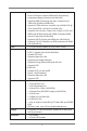
1.2 Specifications Platform CPU Chipset Memory Expansion Slot Graphics - Micro ATX Form Factor - All Solid Capacitor design (H61M-PS4 / H61M-HG4 / H61M-VG4) - Solid Capacitor for CPU power (H61M-VS4) - Supports 3rd and 2nd Generation Intel® CoreTM i7 / i5 / i3 / Xeon® / Pentium® / Celeron® in LGA1155 Package - Supports Intel® Turbo Boost 2.
CPU. - Dual VGA Output: support HDMI and D-Sub ports by Audio LAN Rear Panel I/O Storage Connector independent display controllers (H61M-HG4) - Supports HDMI Technology with max. resolution up to 1920x1200 @ 60Hz (H61M-HG4) - Supports D-Sub with max.
BIOS Feature Support CD Hardware Monitor OS Certifications - 1 x Chassis Intrusion header - 1 x LPC/TPM header - 1 x CPU Fan connectors (4-pin) - 1 x Chassis Fan connector (4-pin) - 1 x 24 pin ATX power connector - 1 x 4 pin 12V power connector - 1 x Front panel audio connector - 1 x SPDIF Out connector - 2 x USB 2.0 headers (support 4 USB 2.0 ports) - 32Mb AMI UEFI Legal BIOS with GUI support - Supports “Plug and Play” - ACPI 1.1 Compliance Wake Up Events - Supports jumperfree - SMBIOS 2.3.
WARNING Please realize that there is a certain risk involved with overclocking, including adjusting the setting in the BIOS, applying Untied Overclocking Technology, or using third-party overclocking tools. Overclocking may affect your system’s stability, or even cause damage to the components and devices of your system. It should be done at your own risk and expense. We are not responsible for possible damage caused by overclocking. CAUTION! 1.
1.3 Unique Features ASRock Extreme Tuning Utility (AXTU) ASRock Extreme Tuning Utility (AXTU) is an all-in-one tool to ne-tune different system functions in a user-friendly interface, which includes Hardware Monitor, Fan Control and XFast RAM. In Hardware Monitor, it shows the major readings of your system. In Fan Control, it shows the fan speed and temperature for you to adjust. In XFast RAM, it fully utilizes the memory space that cannot be used under Windows® OS 32-bit CPU.
ASRock APP Charger If you desire a faster, less restricted way of charging your Apple devices, such as iPhone/iPad/iPod Touch, ASRock has prepared a wonderful solution for you - ASRock APP Charger. Simply install the APP Charger driver, it makes your iPhone charge much quickly from your computer and up to 40% faster than before.
ASRock Crashless BIOS ASRock Crashless BIOS allows users to update their BIOS without fear of failing. If power loss occurs during the BIOS update process, ASRock Crashless BIOS will automatically finish the BIOS update procedure after regaining power. Please note that BIOS files need to be placed in the root directory of your USB disk. Only USB2.0 ports support this feature.
ASRock Restart to UEFI Windows® 8 brings the ultimate boot up experience. The lightning boot up speed makes it hard to access the UEFI setup. ASRock Restart to UEFI technology is designed for those requiring frequent UEFI access. It allows users to easily enter the UEFI automatically when turning on the PC next time. Just simply enable this function; the PC will be assured to access the UEFI directly in the very beginning. ASRock Combo Cooler Option (C.C.O.) Combo Cooler Option (C.C.O.
1.3 Motherboard Layout 1 2 3 PS2 Mouse PS2 Keyboard CPU_FAN1 ATX12V1 HDMI1* USB 2.0 T: USB2 B: USB3 DDR3_B1 (64 bit, 240-pin module) USB 2.
1.4 I/O Panel 1 3 2* 4 5 6 12 1 2 3 4 5 6 11* 9 8* 10 PS/2 Mouse Port (Green) Parallel Port (LPT1) LAN RJ-45 Port Line In (Light Blue) Front Speaker (Lime) Microphone (Pink) 7 8 9 10 11 12 7 USB 2.0 Ports (USB23) HDMI Port (HDMI1) USB 2.0 Ports (USB01) D-Sub Port (VGA1) Serial Port (COM1) PS/2 Keyboard Port (Purple) * The parallel port (LPT1) and serial port (COM1) on the I/O panel are for H61M-PS4 only. * The HDMI port (HDMI1) on the I/O panel is for H61M-HG4 only.
To enable Multi-Streaming function, you need to connect a front panel audio cable to the front panel audio header. Please refer to below steps for the software setting of Multi-Streaming. For Windows® XP: After restarting your computer, you will find “Mixer” tool on your system. Please select “Mixer ToolBox” , click “Enable playback multi-streaming”, and click “ok”.
Chapter 2: Installation This is a Micro ATX form factor motherboard. Before you install the motherboard, study the configuration of your chassis to ensure that the motherboard fits into it. Make sure to unplug the power cord before installing or removing the motherboard. Failure to do so may cause physical injuries to you and damages to motherboard components. 2.1 Screw Holes Place screws into the holes indicated by circles to secure the motherboard to the chassis.
2.3 CPU Installation For the installation of Intel 1155-Pin CPU, please follow the steps below. Load Plate Load Lever Socket Body Contact Array 1155-Pin Socket Overview Before you insert the 1155-Pin CPU into the socket, please check if the CPU surface is unclean or if there is any bent pin on the socket. Do not force to insert the CPU into the socket if above situation is found. Otherwise, the CPU will be seriously damaged. Step 1. Open the socket: Step 1-1.
Step 3. Insert the 1155-Pin CPU: Step 3-1. Hold the CPU by the edge where is black line marked with black line. Step 3-2. Orient the CPU with IHS (Integrated Heat Sink) up. Locate Pin1 and the two orientation key notches. orientation key notch alignment key Pin1 Pin1 alignment key 1155-Pin Socket orientation key notch 1155-Pin CPU For proper inserting, please ensure to match the two orientation key notches of the CPU with the two alignment keys of the socket. Step 3-3.
2.4 Installation of CPU Fan and Heatsink This motherboard is equipped with 1155-Pin socket that supports Intel 1155-Pin CPU. Please adopt the type of heatsink and cooling fan compliant with Intel 1155Pin CPU to dissipate heat. Before you installed the heatsink, you need to spray thermal interface material between the CPU and the heatsink to improve heat dissipation. Ensure that the CPU and the heatsink are securely fastened and in good contact with each other.
2.5 Installation of Memory Modules (DIMM) This motherboard provides two 240-pin DDR3 (Double Data Rate 3) DIMM slots, and supports Dual Channel Memory Technology. For dual channel configuration, you always need to install two identical (the same brand, speed, size and chiptype) memory modules in the DDR3 DIMM slots to activate Dual Channel Memory Technology. Otherwise, it will operate at single channel mode. 1. 2. 3.
2.6 Expansion Slots (PCI Express Slots) There are 2 PCI Express slots on this motherboard. PCIE slots: PCIE1 (PCIE 3.0 x16 slot) is used for PCI Express x16 lane width graphics cards. PCIE2 (PCIE 2.0 x1 slot) is used for PCI Express x1 lane width cards. Only PCIE1 slot supports Gen 3 speed. To run the PCI Express in Gen 3 speed, please install an Ivy Bridge CPU. If you install a Sandy Bridge CPU, the PCI Express will run only at PCI Express Gen 2 speed. Installing an expansion card Step 1. Step 2.
2.7 Jumpers Setup The illustration shows how jumpers are setup. When the jumper cap is placed on pins, the jumper is “Short”. If no jumper cap is placed on pins, the jumper is “Open”. The illustration shows a 3-pin jumper whose pin1 and pin2 are “Short” when jumper cap is placed on these 2 pins. Jumper Setting Clear CMOS Jumper Description (CLRCMOS1) (see p.14, No. 14) Default Clear CMOS Note: CLRCMOS1 allows you to clear the data in CMOS.
2.8 Onboard Headers and Connectors Onboard headers and connectors are NOT jumpers. Do NOT place jumper caps over these headers and connectors. Placing jumper caps over the headers and connectors will cause permanent damage of the motherboard! Serial ATA2 Connectors (SATA_0: see p.14, No. 7) SATA_3 SATA_1 SATA_2 SATA_1 (SATA_1: see p.14, No. 6) (SATA_2: see p.14, No. 9) (SATA_3: see p.14, No.
Front Panel Audio Header GND PRESENCE# MIC_RET OUT_RET (9-pin HD_AUDIO1) (see p.14 No. 18) 1 This is an interface for front panel audio cable that allows convenient connection and control of audio devices. OUT2_L J_SENSE OUT2_R MIC2_R MIC2_L 1. High Definition Audio supports Jack Sensing, but the panel wire on the chassis must support HDA to function correctly. Please follow the instruction in our manual and chassis manual to install your system. 2.
is on when the system is operating. The LED keeps blinking when the system is in S1 sleep state. The LED is off when the system is in S3/S4 sleep state or powered off (S5). HDLED (Hard Drive Activity LED): Connect to the hard drive activity LED on the chassis front panel. The LED is on when the hard drive is reading or writing data. The front panel design may differ by chassis. A front panel module mainly consists of power switch, reset switch, power LED, hard drive activity LED, speaker and etc.
ATX Power Connector (24-pin ATXPWR1) 12 24 1 13 Please connect an ATX power supply to this connector. (see p.14 No. 4) Though this motherboard provides 24-pin ATX power connector, it can still work if you adopt a traditional 20-pin ATX power supply. To use the 20-pin ATX power supply, please plug your power supply along with Pin 1 and Pin 13. 20-Pin ATX Power Supply Installation ATX 12V Power Connector (4-pin ATX12V1) 12 24 1 13 Please connect an ATX 12V power supply to this connector.
LPC/TPM Header (13-pin LPC/TPM1) This connector supports Trusted Platform Module (TPM) (see p.14, No. 16) system, which can securely store keys, digital certificates, passwords, and data. A TPM system also helps enhance network security, protects digital identities, and ensures platform integrity.
2.9 Driver Installation Guide To install the drivers to your system, please insert the support CD to your optical drive first. Then, the drivers compatible to your system can be auto-detected and listed on the support CD driver page. Please follow the order from up to bottom side to install those required drivers. Therefore, the drivers you install can work properly. 2.
STEP 3: Install Windows® XP / XP 64-bit OS on your system. After making a SATA / SATA2 driver diskette, you can start to install Windows® XP / XP 64-bit on your system. At the beginning of Windows® setup, press F6 to install a third-party AHCI driver. When prompted, insert the SATA / SATA2 driver diskette containing the Intel® AHCI driver. After reading the floppy disk, the driver will be presented. Select the driver to install according to the mode you choose and the OS you install.
2.11 ASRock XFast 555 ASRock’s unique XFast 555 Technology includes three tools that allow users to experience huge performance boosts. There is XFast RAM for 5 times better system speed, XFast LAN for 5 times faster LAN speed and XFast USB for 5 times faster USB speed.
2.11.1 ASRock XFast RAM ASRock XFast RAM is a new function that is included in ASRock Extreme Tuning Utility (AXTU). It fully utilizes the memory space that cannot be used under Windows® 32-bit OS. ASRock XFast RAM shortens the loading time of previously visited websites, making web surfing faster than ever. And it also boosts the speed of Adobe Photoshop 5 times faster. Another advantage of ASRock XFast RAM is that it reduces the frequency of accessing your SSDs or HDDs in order to extend their lifespan.
XFast RAM Settings You may find the XFast RAM setup page in the left panel of ASRock Extreme Tuning utility. First select the desired drive and disk size to create a virtual drive. To access more than 4GB of RAM in Windows® 32-bit OS, please leave PAE mode set to ON. In the options section, users may enable and assign the size of a partition for Ready Boost if they’re using a 32-bit OS. We suggest setting the size of Ready Boost one to three times larger than your RAM for optimized performance.
Lastly, select the files that are supposed to go in the virtual drive to speed up the system’s performance. Such as temporary files created by computer programs when they cannot allocate enough memory for its tasks. Or internet cache files including html, images, Cascading Style Sheets and JavaScript scripts from IE, Firefox and Google Chrome. Click Backup XFast RAM if you wish to make a backup. Then click on the APPLY button to activate XFast RAM. Click on STOP if you wish to deactivate XFastRAM.
2.11.2 ASRock XFast LAN ASRock XFast LAN provides several special features for faster internet access. For example, LAN Application Prioritization allows you to configure your application’s priority ideally or add new programs to the priority list. Traffic Shaping helps you watch Youtube HD videos and download files simultaneously without hiccups. And in the status window there’s Real-Time Analysis of Your Data so you can easily recognize the data streams you are transferring currently.
ASRock XFast LAN UI Overview The default status window Low Latency Mode switch arrow down = currently Open slot on (if needed) configuration arrow up = always on Download activity display dialog no arrow = off Open Current Connections window TX shaping indicator Ping time in ms Show/hide slot activation area Number of TCP/ UDP/TCP+UDP connections Variance of ping time Download CPS rate Graphs Transfer rate in % for slots 1-10 Right click for more options 36 Upload CPS rate Upload activity display
Close Windows Hides the status window. Can also be done by double clicking on the status window. Reopen by right clicking on the XFast LAN icon on the bottom right and selecting Open windows. Window settings Users may configure the skin and effects of the user interface. Make the keyboard LEDs display Traffic Shaping information. Or display the XFast LAN status window on a Logitech gamer keyboard instead of Windows desktop.
Adding a new application and changing its priority Click search and choose a new program you wish to add. You can also type in a short description for the program. Set the priority for the program and TX Limit then click Add to confirm. Hit the switch button to change configurations or Delete to remove the application from the priority list.
2.11.3 ASRock XFast USB Not only does ASRock XFast USB boost up the performance of USB 2.0 storage devices, but also USB 3.0 devices.
ASRock XFast USB UI Overview Hide the XFast USB window Select your language Select a connected USB storage device Click to activate/ deactivate Turbo mode Select Normal mode or Turbo mode Click to safely remove the USB hard drive Plug in your USB storage device and XFast USB automatically sets it to Turbo mode! 40
Chapter 3: UEFI SETUP UTILITY 3.1 Introduction This section explains how to use the UEFI SETUP UTILITY to configure your system. The UEFI chip on the motherboard stores the UEFI SETUP UTILITY. You may run the UEFI SETUP UTILITY when you start up the computer. Please press or during the Power-On-Self-Test (POST) to enter the UEFI SETUP UTILITY, otherwise, POST will continue with its test routines.
3.1.2 Navigation Keys Please check the following table for the function description of each navigation key.
H61M-HG4 H61M-VG4 H61M-VS4 43
3.3 OC Tweaker Screen In the OC Tweaker screen, you can set up overclocking features. CPU Configuration CPU Ratio Use this item to change the ratio value of this motherboard. Intel SpeedStep Technology Intel SpeedStep technology is Intel’s new power saving technology. Processors can switch between multiple frequencies and voltage points to enable power saving. The default value is [Enabled]. Configuration options: [Enabled] and [Disabled].
Short Duration Power Limit Use this item to configure short duration power limit in watts. The default value is [Auto]. Primary Plane Current Limit Use this item to configure the maximum instantaneous current allowed for the primary plane. The default value is [Auto]. Secondary Plane Current Limit Use this item to configure the maximum instantaneous current allowed for the secondary plane. The default value is [Auto]. GT OverClocking Support Use this item to enable or disable GT OverClocking Support.
DRAM tRP Use this item to change Row Precharge Time (tRP) Auto/Manual setting. The default is [Auto]. DRAM tRAS Use this item to change RAS# Active Time (tRAS) Auto/Manual setting. The default is [Auto]. Command Rate (CR) Use this item to change Command Rate (CR) Auto/Manual setting. The default is [Auto]. DRAM tWR Use this item to change Write Recovery Time (tWR) Auto/Manual setting. The default is [Auto]. DRAM tRFC Use this item to change Refresh Cyle Time (tRFC) Auto/Manual setting.
MRC Fast Boot Use this item to enable or disable MRC Fast Boot. The default is [Enabled]. Voltage Configuration DRAM Voltage Use this to select DRAM Voltage. The default value is [Auto].
3.4 Advanced Screen In this section, you may set the configurations for the following items: CPU Configuration, North Bridge Configuration, South Bridge Configuration, Storage Configuration, Intel(R) Rapid Start Technology, Intel(R) Smart Connect Technology, Super IO Configuration, ACPI Configuration and USB Configuration. Setting wrong values in this section may cause the system to malfunction.
3.4.1 CPU Configuration Intel Hyper Threading Technology To enable this feature, a computer system with an Intel processor that supports Hyper-Threading technology and an operating system that includes optimization for this technology, such as Microsoft® Windows® XP / VistaTM / 7 / 8 is required. Set to [Enabled] if using Microsoft® Windows® XP, VistaTM, 7, 8, or Linux kernel version 2.4.18 or higher. This option will be hidden if the installed CPU does not support Hyper-Threading technology.
to the IA-32 Intel Architecture. An IA-32 processor with “No Execute (NX) Memory Protection” can prevent data pages from being used by malicious software to execute codes. This option will be hidden if the current CPU does not support No-Excute Memory Protection. Intel Virtualization Technology When this option is set to [Enabled], a VMM (Virtual Machine Architecture) can utilize the additional hardware capabilities provided by Vanderpool Technology.
3.4.2 North Bridge Configuration Primary Graphics Adapter This allows you to select [Onboard] or [PCI Express] as the boot graphic adapter priority. The default value is [PCI Express]. VT-d Use this to enable or disable Intel® VT-d technology (Intel® Virtualization Technology for Directed I/O). The default value of this feature is [Disabled]. PCIE1 Link Speed This allows you to select PCIE1 Link Speed. The default value is [Auto].
3.4.3 South Bridge Configuration Onboard HD Audio Select [Auto], [Enabled] or [Disabled] for the onboard HD Audio feature. If you select [Auto], the onboard HD Audio will be disabled when PCI Sound Card is plugged. Front Panel Select [Auto] or [Disabled] for the onboard HD Audio Front Panel. Onboard LAN This allows you to enable or disable the Onboard LAN feature. Restore on AC/Power Loss This allows you to set the power state after an unexpected AC/power loss.
3.4.4 Storage Configuration SATA Controller(s) Use this item to enable or disable the SATA Controller feature. SATA Mode Selection Use this to select SATA mode. Configuration options: [IDE Mode], [AHCI Mode] and [Disabled]. The default value is [AHCI Mode]. AHCI (Advanced Host Controller Interface) supports NCQ and other new features that will improve SATA disk performance but IDE mode does not have these advantages.
3.4.5 Intel(R) Rapid Start Technology Intel(R) Rapid Start Technology Use this item to enable or disable Intel(R) Rapid Start Technology. Intel(R) Rapid Start Technology is a new zero power hibernation mode which allows users to resume in just 5-6 seconds. The default is [Enabled]. Entry After Select a time to enable RTC wake timer at S3 entry. The default is [10 minutes]. Active Page Threshold Support This allows you to enable or disable Active Page Threshold Support. The default is [Disabled].
3.4.6 Intel(R) Smart Connect Technology Intel(R) Smart Connect Technology Use this item to enable or disable Intel(R) Smart Connect Technology. Intel(R) Smart Connect Technology keeps your e-mail and social networks, such as Twitter, Facebook, etc. updated automatically while the computer is in sleep mode. The default is [Enabled].
3.4.7 Super IO Configuration Serial Port Use this item to enable or disable the onboard serial port. Port Address Use this item to set the address for the onboard serial port. Configuration options: [3F8 / IRQ4] and [3E8 / IRQ4]. Infrared Port Use this item to enable or disable the onboard infrared port. * Serial Port is for H61M-PS4 only.
3.4.8 ACPI Configuration Suspend to RAM Use this item to select whether to auto-detect or disable the Suspend-toRAM feature. Selecting [Auto] will enable this feature if the OS supports it. Check Ready Bit Use this item to enable or disable the feature Check Ready Bit. ACPI HPET Table Use this item to enable or disable ACPI HPET Table. The default value is [Enabled]. Please set this option to [Enabled] if you plan to use this motherboard to submit Windows® certification.
CSM Please disable CSM when you enable Fast Boot option. The default value is [Enabled]. 3.4.9 USB Configuration USB 2.0 Controller Use this item to enable or disable the use of USB 2.0 controller. Legacy USB Support Use this option to select legacy support for USB devices. There are four configuration options: [Enabled], [Auto], [Disabled] and [UEFI Setup Only]. The default value is [Enabled].
3.5 Tool OMG(Online Management Guard) Administrators are able to establish an internet curfew or restrict internet access at specified times via OMG. You may schedule the starting and ending hours of internet access granted to other users. In order to prevent users from bypassing OMG, guest accounts without permission to modify the system time are required. UEFI Update Utility Instant Flash Instant Flash is a UEFI flash utility embedded in Flash ROM.
Network Configuration Internet Setting Use this item to set up the internet connection mode. Configuration options: [DHCP (Auto IP)] and [PPPOE]. UEFI Download Server Use this item to select UEFI firmware download server for Internet Flash. Configuration options: [Asia], [Europe], [USA] and [China]. Dehumidifier Function Users may prevent motherboard damages due to dampness by enabling “Dehumidifier Function”.
3.6 Hardware Health Event Monitoring Screen In this section, it allows you to monitor the status of the hardware on your system, including the parameters of the CPU temperature, motherboard temperature, CPU fan speed, chassis fan speed, and the critical voltage. CPU Fan 1 Setting This allows you to set the CPU fan 1 speed. Configuration options: [Full On] and [Automatic Mode]. The default is value [Full On]. Chassis Fan 1 Setting This allows you to set the Chassis fan 1 speed.
3.7 Boot Screen In this section, it will display the available devices on your system for you to configure the boot settings and the boot priority. Fast Boot Fast Boot minimizes your computer’s boot time. There are three configuration options: [Disabled], [Fast] and [Ultra Fast]. The default value is [Disabled]. Please refer to below descriptions for the details of these three options: [Disabled] - Disable Fast Boot. [Fast] - The only restriction is you may not boot by using an USB flash drive.
Full Screen Logo Use this item to enable or disable OEM Logo. The default value is [Enabled]. AddOn ROM Display Use this option to adjust AddOn ROM Display. If you enable the option “Full Screen Logo” but you want to see the AddOn ROM information when the system boots, please select [Enabled]. Configuration options: [Enabled] and [Disabled]. The default value is [Enabled]. Boot Failure Guard Enable or disable the feature of Boot Failure Guard.
3.8 Security Screen In this section, you may set or change the supervisor/user password for the system. For the user password, you may also clear it. Secure Boot Use this to enable or disable Secure Boot. The default value is [Disabled].
3.9 Exit Screen Save Changes and Exit When you select this option, the following message “Save configuration changes and exit setup?” will pop-out. Select [Yes] to save the changes and exit the UEFI SETUP UTILITY. Discard Changes and Exit When you select this option, the following message “Discard changes and exit setup?” will pop-out. Select [Yes] to exit the UEFI SETUP UTILITY without saving any changes. Discard Changes When you select this option, the following message “Discard changes?” will pop-out.
Chapter 4: Software Support 4.1 Install Operating System This motherboard supports various Microsoft® Windows® operating systems: 8 / 8 64-bit / 7 / 7 64-bit / VistaTM / VistaTM 64-bit / XP / XP 64-bit. Because motherboard settings and hardware options vary, use the setup procedures in this chapter for general reference only. Refer to your OS documentation for more information. 4.
Installing OS on a HDD Larger Than 2TB This motherboard is adopting UEFI BIOS that allows Windows® OS to be installed on a large size HDD (>2TB). Please follow below procedure to install the operating system. 1. Please make sure to use Windows® VistaTM 64-bit (with SP1 or above), Windows® 7 64-bit or Windows® 8 64-bit. 2. Press or at system POST. Set AHCI Mode in UEFI Setup Utility > Advanced > Storage Configuration > SATA Mode. 3.