H77M-ITX User Manual Version 1.2 Published June 2013 Copyright©2013 ASRock INC. All rights reserved.
Copyright Notice: No part of this manual may be reproduced, transcribed, transmitted, or translated in any language, in any form or by any means, except duplication of documentation by the purchaser for backup purpose, without written consent of ASRock Inc. Products and corporate names appearing in this manual may or may not be registered trademarks or copyrights of their respective companies, and are used only for identiication or explanation and to the owners’ beneit, without intent to infringe.
Contents 1 Introduction......................................................... 7 1.1 1.2 1.3 1.4 Package Contents ......................................................... Speciications................................................................. Motherboard Layout....................................................... I/O Panel ...................................................................... 7 8 13 14 2 Installation ........................................................... 16 2.
3 UEFI SETUP UTILITY ................................................. 36 3.1 Introduction .................................................................... 36 3.2 3.3 3.4 3.5 3.6 3.7 3.8 3.1.1 UEFI Menu Bar .................................................... 3.1.2 Navigation Keys ................................................... Main Screen................................................................... OC Tweaker Screen ...................................................... Advanced Screen....
Chapter 1: Introduction Thank you for purchasing ASRock H77M-ITX motherboard, a reliable motherboard produced under ASRock’s consistently stringent quality control. It delivers excellent performance with robust design conforming to ASRock’s commitment to quality and endurance. In this manual, chapter 1 and 2 contains introduction of the motherboard and stepby-step guide to the hardware installation. Chapter 3 and 4 contains the coniguration guide to BIOS setup and information of the Support CD.
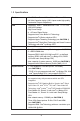
1.2 Specifications Platform CPU Chipset Memory Expansion Slot Graphics - Mini-ITX Form Factor: 6.7-in x 6.7-in, 17.0 cm x 17.0 cm - All Solid Capacitor design (100% Japan-made high-quality Conductive Polymer Capacitors) - Supports 3rd and 2nd Generation Intel® CoreTM i7 / i5 / i3 in LGA1155 Package - Digi Power Design - 4 + 2 Power Phase Design - Supports Intel® Turbo Boost 2.
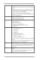
Audio LAN Rear Panel I/O SATA3 USB3.0 - Supports DVI with max. resolution up to 1920x1200 @ 60Hz - Supports D-Sub with max. resolution up to 2048x1536 @ 75Hz - Supports Auto Lip Sync, Deep Color (12bpc), xvYCC and HBR (High Bit Rate Audio) with HDMI (Compliant HDMI monitor is required) (see CAUTION 7) - Supports HDCP function with DVI and HDMI ports - Supports Full HD 1080p Blu-ray (BD) / HD-DVD playback with DVI and HDMI ports - 7.
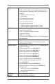
Connector BIOS Feature Support CD Unique Feature Hardware Monitor - 2 x SATA2 3.0 Gb/s connectors, support RAID (RAID 0, RAID 1, RAID 5, RAID 10, Intel Rapid Storage and Intel Smart Response Technology), NCQ, AHCI and Hot Plug functions - 2 x SATA3 6.0Gb/s connectors - 1 x CIR header - CPU/Chassis FAN connector - 24 pin ATX power connector - 4 pin 12V power connector - Front panel audio connector - 1 x USB 2.0 header (supports 2 USB 2.0 ports) - 1 x USB 3.0 header (supports 2 USB 3.
OS Certiications - CPU Fan Tachometer - Chassis Fan Tachometer - CPU/Chassis Quiet Fan (Allows Chassis Fan Speed AutoAdjust by CPU Temperature) - CPU/Chassis Fan Multi-Speed Control - Voltage Monitoring: +12V, +5V, +3.3V, CPU Vcore - Microsoft® Windows® 7 / 7 64-bit / VistaTM / VistaTM 64-bit / XP / XP 64-bit compliant (see CAUTION 21) - FCC, CE, WHQL - ErP/EuP Ready (ErP/EuP ready power supply is required) (see CAUTION 22) * For detailed product information, please visit our website: http://www.asrock.
xvYCC and Deep Color are only supported under Windows® 7 64-bit / 7. Deep Color mode will be enabled only if the display supports 12bpc in EDID. HBR is supported under Windows® 7 64-bit / 7 / VistaTM 64-bit / VistaTM. 8. For microphone input, this motherboard supports both stereo and mono modes. For audio output, this motherboard supports 2-channel, 4-channel, 6-channel, and 8-channel modes. Please check the table on page 14 for proper connection. 9.
12. ASRock SmartView, a new function for internet browsers, is the smart start page for IE that combines your most visited web sites, your history, your Facebook friends and your real-time newsfeed into an enhanced view for a more personal Internet experience. ASRock motherboards are exclusively equipped with the ASRock SmartView utility that helps you keep in touch with friends on-the-go.
19. ASRock On/Off Play Technology allows users to enjoy the great audio experience from the portable audio devices, such like MP3 player or mobile phone to your PC, even when the PC is turned off (or in ACPI S5 mode)! This motherboard also provides a free 3.5mm audio cable (optional) that ensures users the most convenient computing environment. 20. While CPU overheat is detected, the system will automatically shutdown.
1.3 Motherboard Layout 1 2 56 4 3 7 8 10 11 9 17.0cm (6.7 in) SATA_0 SATA_2 SATA_1 SATA_3 ATXPWR1 PS2 Keyboard Super I/O USB 2.0 T: USB0 B: USB1 64Mb BIOS PLED PWRBTN 1 HDLED RESET PANEL1 19 USB4_5 1 CIR1 1 1 HDMI1 ATX12V1 CLRCMOS1 ESATA1 USB 2.0 T: USB2 B: USB3 X Fast RAM 17 CHA_FAN1 16 CPU_FAN1 USB 3.0 T: USB1 B: USB2 Top: RJ-45 17.0cm (6.
1.4 I/O Panel 1 3 2 4 5 7 6 8 9 15 1 2 3 *4 5 6 7 ** 8 13 14 12 USB 2.0 Ports (USB01) D-Sub Port (VGA1) USB 2.0 Ports (USB23) LAN RJ-45 Port Central / Bass (Orange) Rear Speaker (Black) Line In (Light Blue) Front Speaker (Lime) 9 10 11 12 13 14 15 11 10 Microphone (Pink) Optical SPDIF Out Port USB 3.0 Ports (USB3_12) eSATA2 Connector HDMI Port (HDMI1) DVI-D Port (DVI1) PS/2 Keyboard Port (Purple) * There are two LED next to the LAN port.
To enable Multi-Streaming function, you need to connect a front panel audio cable to the front panel audio header. After restarting your computer, you will ind “Mixer” tool on your system. Please select “Mixer ToolBox” , click “Enable playback multi-streaming”, and click “ok”. Choose “2CH”, “4CH”, “6CH”, or “8CH” and then you are allowed to select “Realtek HDA Primary output” to use Rear Speaker, Central/Bass, and Front Speaker, or select “Realtek HDA Audio 2nd output” to use front panel audio.
Chapter 2: Installation This is a Mini-ITX form factor (6.7" x 6.7", 17.0 x 17.0 cm) motherboard. Before you install the motherboard, study the coniguration of your chassis to ensure that the motherboard its into it. Make sure to unplug the power cord before installing or removing the motherboard. Failure to do so may cause physical injuries to you and damages to motherboard components. 2.1 Screw Holes Place screws into the holes indicated by circles to secure the motherboard to the chassis.
2.3 CPU Installation In order to provide the LGA 1155 CPU sockets more protection and make the installation process easier, ASRock has added a new protection cover on top of the load plate to replace the former PnP caps that were under the load plate. For the installation of Intel® 1155-Pin CPUs with the new protection cover, please follow the steps below.
orientation key notch alignment key Pin1 Pin1 alignment key 1155-Pin Socket orientation key notch 1155-Pin CPU For proper installation, please ensure to match the two orientation key notches of the CPU with the two alignment keys of the socket. Step 2-3. Carefully place the CPU into the socket. Step 2-4. Verify that the CPU is within the socket and properly mated to the orient keys. Step 3. Close the socket: Step 3-1. Flip the load plate onto the IHS. Step 3-2.
2.4 Installation of CPU Fan and Heatsink This motherboard is equipped with 1155-Pin socket that supports Intel 1155-Pin CPUs. Please adopt the type of heatsink and cooling fan compliant with Intel 1155Pin CPU to dissipate heat. Before you install the heatsink, you need to spray thermal interface material between the CPU and the heatsink to improve heat dissipation. Ensure that the CPU and the heatsink are securely fastened and in good contact with each other.
2.5 Installation of Memory Modules (DIMM) This motherboard provides two 240-pin DDR3 (Double Data Rate 3) DIMM slots, and supports Dual Channel Memory Technology. For dual channel configuration, you always need to install two identical (the same brand, speed, size and chiptype) memory modules in the DDR3 DIMM slots to activate Dual Channel Memory Technology. Otherwise, it will operate at single channel mode. 1. 2. 3.
2.6 Expansion Slot (PCI Express Slot) There is 1 PCI Express slot on this motherboard. PCIE slots: PCIE1 (PCIE 3.0 x16 slot) is used for PCI Express x16 lane width graphics cards. To run the PCI Express in Gen 3 speed, please install an Ivy Bridge CPU. If you install a Sandy Bridge CPU, the PCI Express will run only at PCI Express Gen 2 speed. Installing an expansion card Step 1. Step 2. Step 3. Step 4. Step 5. Step 6.
2.7 Dual Monitor and Surround Display Features Dual Monitor Feature This motherboard supports dual monitor feature. With the internal VGA output support (DVI-D, D-Sub and HDMI), you can easily enjoy the beneits of dual monitor feature without installing any add-on VGA cards to this motherboard. This motherboard also provides independent display controllers for DVI-D, D-Sub and HDMI to support dual VGA output so that DVI-D, D-sub and HDMI can drive same or different display contents.
Surround Display Feature This motherboard supports surround display upgrade. With the internal VGA output support (DVI-D, D-Sub and HDMI) and external add-on PCI Express VGA cards, you can easily enjoy the beneits of surround display feature. Please refer to the following steps to set up a surround display environment: 1. Install the PCI Express VGA cards on PCIE1 slot. Please refer to page 21 for proper expansion card installation procedures. 2.
For Windows® 7 / 7 64-bit / VistaTM / VistaTM 64-bit OS: Right click the desktop, choose “Personalize”, and select the “Display Settings” tab so that you can adjust the parameters of the multi-monitors according to the steps below. A. Click the number ”2” icon. B. Click the items “This is my main monitor” and “Extend the desktop onto this monitor”. C. Click “OK” to save your change. D. Repeat steps A through C for the display icons identiied by the number three to four. 6. Use Surround Display.
2.8 ASRock Smart Remote Installation Guide ASRock Smart Remote is only used for ASRock motherboards with CIR header. Please refer to below procedures for the quick installation and usage of ASRock Smart Remote. Step1. Find the CIR header located next to the USB 2.0 header on ASRock motherboard. USB 2.0 header (9-pin, black) CIR header (4-pin, gray) Step2. Connect the front USB cable to the USB 2.0 header (as below, pin 1-5) and the CIR header.
2.9 Jumpers Setup The illustration shows how jumpers are setup. When the jumper cap is placed on pins, the jumper is “Short”. If no jumper cap is placed on pins, the jumper is “Open”. The illustration shows a 3-pin jumper whose pin1 and pin2 are “Short” when jumper cap is placed on these 2 pins. Jumper Clear CMOS Jumper Setting Description (CLRCMOS1) (see p.13, No. 18) Default Clear CMOS Note: CLRCMOS1 allows you to clear the data in CMOS.
2.10 Onboard Headers and Connectors Onboard headers and connectors are NOT jumpers. Do NOT place jumper caps over these headers and connectors. Placing jumper caps over the headers and connectors will cause permanent damage of the motherboard! Serial ATA2 Connectors (SATA_2: see p.13, No. 4) These two Serial ATA2 (SATA2) SATA_2 connectors support SATA data (SATA_3: see p.13, No. 5) cables for internal storage devices. The current SATA2 interface allows up to 3.0 Gb/s data transfer rate.
USB 3.0 Header IntA_P0_D+ IntA_P0_DGND IntA_P0_SSTX+ IntA_P0_SSTXGND IntA_P0_SSRX+ IntA_P0_SSRXVbus (19-pin USB3_3_4) (see p.13, No. 12) 1 Besides two default USB 3.0 ports on the I/O panel, there is one USB 3.0 header on this motherboard. This USB 3.0 header can support two USB 3.0 ports. Vbus IntA_P1_SSRXIntA_P1_SSRX+ GND IntA_P1_SSTXIntA_P1_SSTX+ GND IntA_P1_DIntA_P1_D+ DUMMY Consumer Infrared Module Header This header can be used to connect the remote controller receiver. (4-pin CIR1) (see p.
System Panel Header This header accommodates (9-pin PANEL1) several system front panel (see p.13, No. 8) functions. Connect the power switch, reset switch and system status indicator on the chassis to this header according to the pin assignments below. Note the positive and negative pins before connecting the cables. PWRBTN (Power Switch): Connect to the power switch on the chassis front panel. You may conigure the way to turn off your system using the power switch.
Though this motherboard provides 4-Pin CPU fan (Quiet Fan) support, the 3-Pin CPU fan still can work successfully even without the fan speed control function. If you plan to connect the 3-Pin CPU fan to the CPU fan connector on this motherboard, please connect it to Pin 1-3. Pin 1-3 Connected 3-Pin Fan Installation ATX Power Connector (24-pin ATXPWR1) (see p.13, No. 9) Please connect an ATX power 24 13 12 1 supply to this connector.
2.11 Serial ATA (SATA) / Serial ATA2 (SATA2) / Serial ATA3 (SATA3) Hard Disks Installation This motherboard adopts Intel® H77 chipset that supports Serial ATA (SATA) / Serial ATA2 (SATA2) / Serial ATA3 (SATA3) hard disks and RAID (RAID 0, RAID 1, RAID 5, RAID 10, Intel Rapid Storage and Intel Smart Response Technology) functions. You may install SATA / SATA2 / SATA3 hard disks on this motherboard for internal storage devices. This section will guide you to install the SATA / SATA2 / SATA3 hard disks.
2.13 SATA / SATA2 / SATA3 HDD Hot Plug Feature and Operation Guide This motherboard supports Hot Plug feature for SATA / SATA2 / SATA3 HDD in RAID / AHCI mode. Please read below operation guide of Hot Plug feature carefully. Before you process the SATA / SATA2 / SATA3 HDD Hot Plug, please check below cable accessories from the motherboard gift box pack. A. 7-pin SATA data cable B. SATA power cable with SATA 15-pin power connector interface A. SATA data cable (Red) SATA 7-pin connector B.
How to Hot Plug a SATA / SATA2 / SATA3 HDD: Points of attention, before you process the Hot Plug: Please do follow below instruction sequence to process the Hot Plug, improper procedure will cause the SATA / SATA2 / SATA3 HDD damage and data loss. Step 1 Please connect SATA power cable 1x4pin end (White) to the power supply 1x4-pin cable. Step 2 Connect SATA data cable to the motherboard’s SATA2 / SATA3 connector.
2.14 Driver Installation Guide To install the drivers to your system, please insert the support CD to your optical drive irst. Then, the drivers compatible to your system can be auto-detected and listed on the support CD driver page. Please follow the order from up to bottom side to install those required drivers. Therefore, the drivers you install can work properly. 2.
2.16 Installing Windows® 7 / 7 64-bit / VistaTM / VistaTM 64-bit / XP / XP 64-bit Without RAID Functions If you want to install Windows® 7 / 7 64-bit / VistaTM / VistaTM 64-bit / XP / XP 64bit OS on your SATA / SATA2 / SATA3 HDDs without RAID functions, please follow below procedures according to the OS you install. 2.16.
Chapter 3: UEFI SETUP UTILITY 3.1 Introduction This section explains how to use the UEFI SETUP UTILITY to conigure your system. The UEFI chip on the motherboard stores the UEFI SETUP UTILITY. You may run the UEFI SETUP UTILITY when you start up the computer. Please press or during the Power-On-Self-Test (POST) to enter the UEFI SETUP UTILITY, otherwise, POST will continue with its test routines.
3.1.2 Navigation Keys Please check the following table for the function description of each navigation key.
3.3 OC Tweaker Screen In the OC Tweaker screen, you can set up overclocking features. CPU Coniguration CPU Turbo Ratio Use this item to change the ratio value of this motherboard. Intel SpeedStep Technology Intel SpeedStep technology is Intel’s new power saving technology. Processors can switch between multiple frequencies and voltage points to enable power saving. The default value is [Enabled]. Coniguration options: [Enabled] and [Disabled].
Short Duration Power Limit Use this item to conigure short duration power limit in watts. The default value is [Auto]. Primary Plane Current Limit Use this item to conigure the maximum instantaneous current allowed for the primary plane. The default value is [Auto]. Secondary Plane Current Limit Use this item to conigure the maximum instantaneous current allowed for the secondary plane. The default value is [Auto]. GT OverClocking Support Use this item to enable or disable GT OverClocking Support.
DRAM tRP Use this item to change Row Precharge Time (tRP) Auto/Manual setting. The default is [Auto]. DRAM tRAS Use this item to change RAS# Active Time (tRAS) Auto/Manual setting. The default is [Auto]. Command Rate (CR) Use this item to change Command Rate (CR) Auto/Manual setting. The default is [Auto]. DRAM tWR Use this item to change Write Recovery Time (tWR) Auto/Manual setting. The default is [Auto]. DRAM tRFC Use this item to change Refresh Cyle Time (tRFC) Auto/Manual setting.
MRC Fast Boot Use this item to enable or disable MRC Fast Boot. The default is [Enabled]. Voltage Coniguration CPU Core Voltage Use this to select CPU Core Voltage. The default value is [Auto]. CPU Load-Line Calibration CPU Load-Line Calibration helps prevent CPU voltage droop when the system is under heavy load. IGPU Voltage Use this to select IGPU Voltage. The default value is [Auto].
3.4 Advanced Screen In this section, you may set the conigurations for the following items: CPU Coniguration, North Bridge Coniguration, South Bridge Coniguration, Storage Coniguration, Intel(R) Rapid Start Technology, Intel(R) Smart Connect Technology, ACPI Coniguration and USB Coniguration. Setting wrong values in this section may cause the system to malfunction. Instant Flash Instant Flash is a UEFI lash utility embedded in Flash ROM.
3.4.1 CPU Configuration Intel Hyper Threading Technology To enable this feature, a computer system with an Intel processor that supports Hyper-Threading technology and an operating system that includes optimization for this technology, such as Microsoft® Windows® XP / VistaTM / 7 is required. Set to [Enabled] if using Microsoft® Windows® XP, VistaTM, 7, or Linux kernel version 2.4.18 or higher. This option will be hidden if the installed CPU does not support Hyper-Threading technology.
to the IA-32 Intel Architecture. An IA-32 processor with “No Execute (NX) Memory Protection” can prevent data pages from being used by malicious software to execute codes. This option will be hidden if the current CPU does not support No-Excute Memory Protection. Intel Virtualization Technology When this option is set to [Enabled], a VMM (Virtual Machine Architecture) can utilize the additional hardware capabilities provided by Vanderpool Technology.
3.4.2 North Bridge Configuration Primary Graphics Adapter This allows you to select [Onboard] or [PCI Express] as the boot graphic adapter priority. The default value is [PCI Express]. VT-d Use this to enable or disable Intel® VT-d technology (Intel® Virtualization Technology for Directed I/O). The default value of this feature is [Disabled]. PCIE1 Link Speed This allows you to select PCIE1 Link Speed. The default value is [Auto]. Share Memory This allows you to set onboard VGA share memory feature.
3.4.3 South Bridge Configuration Onboard HD Audio Select [Auto], [Enabled] or [Disabled] for the onboard HD Audio feature. If you select [Auto], the onboard HD Audio will be disabled when PCI Sound Card is plugged. Front Panel Select [Auto] or [Disabled] for the onboard HD Audio Front Panel. On/Off Play Use this item to enable or disable On/Off Play Technology. The default value is [Enabled]. When On/Off Play is enabled, Deep Sleep will be disabled.
3.4.4 Storage Configuration SATA Controller(s) Use this item to enable or disable the SATA Controller feature. SATA Mode Selection Use this to select SATA mode. Coniguration options: [IDE Mode], [AHCI Mode] and [RAID Mode]. The default value is [AHCI Mode]. AHCI (Advanced Host Controller Interface) supports NCQ and other new features that will improve SATA disk performance but IDE mode does not have these advantages.
3.4.5 Intel(R) Rapid Start Technology Intel(R) Rapid Start Technology Use this item to enable or disable Intel(R) Rapid Start Technology. Intel(R) Rapid Start Technology is a new zero power hibernation mode which allows users to resume in just 5-6 seconds. The default is [Enabled]. Entry on S3 RTC Wake Use this item to enable or disable Intel Rapid Start invocation upon S3 RTC wake. The default is [Enabled]. Entry After Select a time to enable RTC wake timer at S3 entry. The default is [10 minutes].
3.4.6 Intel(R) Smart Connect Technology Intel(R) Smart Connect Technology Use this item to enable or disable Intel(R) Smart Connect Technology. Intel(R) Smart Connect Technology keeps your e-mail and social networks, such as Twitter, Facebook, etc. updated automatically while the computer is in sleep mode. The default is [Disabled].
3.4.7 ACPI Configuration Suspend to RAM Use this item to select whether to auto-detect or disable the Suspend-toRAM feature. Selecting [Auto] will enable this feature if the OS supports it. Check Ready Bit Use this item to enable or disable the feature Check Ready Bit. ACPI HPET Table Use this item to enable or disable ACPI HPET Table. The default value is [Enabled]. Please set this option to [Enabled] if you plan to use this motherboard to submit Windows® VistaTM certiication.
OMG (Online Management Guard) Administrators are able to establish an internet curfew or restrict internet access at speciied times via OMG. You may choose from [Everyday], [Day of the week] or [Weekdays and weekends], then schedule the starting and ending hours of internet access granted to other users. In order to prevent users from bypassing OMG, guest accounts without permission to modify the system time are required. 3.4.8 USB Configuration USB 2.
3.5 Hardware Health Event Monitoring Screen In this section, it allows you to monitor the status of the hardware on your system, including the parameters of the CPU temperature, motherboard temperature, CPU fan speed, chassis fan speed, and the critical voltage. CPU Fan 1 Setting This allows you to set CPU fan 1’s speed. Coniguration options: [Full On] and [Automatic Mode]. The default value is [Full On]. Chassis Fan 1 Setting This allows you to set chassis fan 1’s speed.
3.6 Boot Screen In this section, it will display the available devices on your system for you to conigure the boot settings and the boot priority. Setup Prompt Timeout This shows the number of seconds to wait for setup activation key. 65535(0XFFFF) means indeinite waiting. Bootup Num-Lock If this item is set to [On], it will automatically activate the Numeric Lock function after boot-up. PCI ROM Priority Use this item to adjust PCI ROM Priority. The default value is [Legacy ROM].
3.7 Security Screen In this section, you may set or change the supervisor/user password for the system. For the user password, you may also clear it.
3.8 Exit Screen Save Changes and Exit When you select this option, the following message “Save coniguration changes and exit setup?” will pop-out. Select [Yes] to save the changes and exit the UEFI SETUP UTILITY. Discard Changes and Exit When you select this option, the following message “Discard changes and exit setup?” will pop-out. Select [Yes] to exit the UEFI SETUP UTILITY without saving any changes. Discard Changes When you select this option, the following message “Discard changes?” will pop-out.
Chapter 4: Software Support 4.1 Install Operating System This motherboard supports various Microsoft® Windows® operating systems: 7 / 7 64-bit / VistaTM / VistaTM 64-bit / XP / XP 64-bit. Because motherboard settings and hardware options vary, use the setup procedures in this chapter for general reference only. Refer to your OS documentation for more information. 4.
Installing OS on a HDD Larger Than 2TB in AHCI Mode This motherboard adopts UEFI BIOS that allows Windows® OS to be installed on a large size HDD (>2TB). Please follow the procedures below to install the operating system. 1. Please make sure to use Windows® VistaTM 64-bit (with SP2 or above) or Windows® 7 64-bit (with SP1 or above). 2. Press or at system POST. Set AHCI Mode in UEFI Setup Utility > Advanced > Storage Coniguration > SATA Mode. 3.
Installing OS on a HDD Larger Than 2TB in RAID Mode This motherboard adopts UEFI BIOS that allows Windows® OS to be installed on a large size HDD (>2TB). Please follow the procedures below to install the operating system. 1. Please make sure to use Windows® VistaTM 64-bit (with SP2 or above) or Windows® 7 64-bit (with SP1 or above). 2. Copy Intel® RAID drivers into a USB lash disk.
E. Please keep the USB lash disk installed until the system's irst reboot. F. Continue to install OS by following the Windows® instructions. 5. Follow Windows® Installation Guide to install OS. If you install Windows® 7 64-bit / VistaTM 64-bit on a large hard disk (ex. Disk volume > 2TB), it may take more time to boot into Windows® or install driver/utilities. If you encounter this problem, you will need to follow the instructions below to ix this problem.
B. Disable “Volume Shadow Copy” service. a. Type “computer management” in the Start Menu, then press “Enter”. b. Go to “Services and Applications>Services”; Then double click “Volume Shadow Copy”.
c. Set “Startup type” to “Disable” then Click “OK”. C. Reboot your system. D. After reboot, please start to install motherboard drivers and utilities. Windows® 7 64-bit: A. Please request the hotix KB2505454 through this link: http://support.microsoft.com/kb/2505454/ B. After installing Windows® 7 64-bit, install the hotix kb2505454. (This may take a long time; >30 mins.) C. Reboot your system. (It may take about 5 minutes to reboot.) D. Windows® will install this hotix then reboot by itself. E.