User Manual
Version 1.0 Published October 2013 Copyright©2013 ASRock INC. All rights reserved. Copyright Notice: No part of this documentation may be reproduced, transcribed, transmitted, or translated in any language, in any form or by any means, except duplication of documentation by the purchaser for backup purpose, without written consent of ASRock Inc.
Contents Chapter 1 Introduction 1 1.1 Package Contents 1 1.2 Specifications 2 1.3 Unique Features 6 1.4 Motherboard Layout 9 1.5 I/O Panel 11 Chapter 2 Installation 12 2.1 Installing the CPU 13 2.2 Installing the CPU Fan and Heatsink 16 2.3 Installing Memory Modules (DIMM) 17 2.4 Expansion Slots (PCI Express Slots) 19 2.5 Jumpers Setup 20 2.6 Onboard Headers and Connectors 21 Chapter 3 Software and Utilities Operation 25 3.1 Installing Drivers 25 3.
.2 Main Screen 40 4.3 OC Tweaker Screen 41 4.4 Advanced Screen 49 4.4.1 CPU Configuration 50 4.4.2 Chipset Configuration 52 4.4.3 Storage Configuration 54 4.4.4 Intel® Smart Connect Technology 55 4.4.5 Super IO Configuration 56 4.4.6 ACPI Configuration 58 4.4.7 USB Configuration 60 4.4.8 Trusted Computing 61 4.5 Tools 62 4.6 Hardware Health Event Monitoring Screen 65 4.7 Boot Screen 66 4.8 Security Screen 69 4.
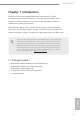
H81 Pro BTC Chapter 1 Introduction Thank you for purchasing ASRock H81 Pro BTC motherboard, a reliable motherboard produced under ASRock’s consistently stringent quality control. It delivers excellent performance with robust design conforming to ASRock’s commitment to quality and endurance. In this manual, Chapter 1 and 2 contains the introduction of the motherboard and step-by-step installation guides. Chapter 3 contains the operation guide of the software and utilities.
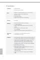
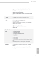
1.2 Specifications English 2 Platform • ATX Form Factor • All Solid Capacitor design CPU th TM • Supports 4 Generation Intel® Core i7 / i5 / i3 / Xeon® / Pentium® / Celeron® in LGA1150 Package • Digi Power design • 4 Power Phase design • Supports Intel® Turbo Boost 2.0 Technology Chipset • Intel® H81 Memory • Dual Channel DDR3 Memory Technology • 2 x DDR3 DIMM Slots • Supports DDR3 1600/1333/1066 non-ECC, un-buffered memory • Max.
H81 Pro BTC • Supports Auto Lip Sync, Deep Color (12bpc), xvYCC and HBR (High Bit Rate Audio) with HDMI Port (Compliant HDMI monitor is required) • Supports HDCP with HDMI Port • Supports Full HD 1080p Blu-ray (BD) playback with HDMI Port Audio • 5.1 CH HD Audio (Realtek ALC662 Audio Codec) LAN • • • • • • • Rear Panel I/O • • • • • • • • • Storage • 2 x SATA3 6.0 Gb/s Connectors, support NCQ, AHCI and Hot Plug • 2 x SATA2 3.
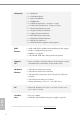
• • • • • • • • • • • • • 1 x IR Header BIOS Feature • • • • 32Mb AMI UEFI Legal BIOS with multilingual GUI support ACPI 1.1 Compliant wake up events SMBIOS 2.3.1 support CPU, DRAM, PCH 1.
H81 Pro BTC Please realize that there is a certain risk involved with overclocking, including adjusting the setting in the BIOS, applying Untied Overclocking Technology, or using thirdparty overclocking tools. Overclocking may affect your system’s stability, or even cause damage to the components and devices of your system. It should be done at your own risk and expense. We are not responsible for possible damage caused by overclocking. English 1.
1.3 Unique Features ASRock A-Tuning A-Tuning is ASRock’s multi purpose software suite with a new interface, more new features and improved utilities, including XFast RAM, Dehumidifier, Good Night LED, FAN-Tastic Tuning, OC Tweaker and a whole lot more. ASRock Instant Flash ASRock Instant Flash is a BIOS flash utility embedded in Flash ROM. This convenient BIOS update tool allows you to update the system BIOS in a few clicks without preparing an additional floppy diskette or other complicated flash utility.
H81 Pro BTC ASRock Crashless BIOS ASRock Crashless BIOS allows users to update their BIOS without fear of failing. If power loss occurs during the BIOS updating process, ASRock Crashless BIOS will automatically finish the BIOS update procedure after regaining power. Please note that BIOS files need to be placed in the root directory of your USB disk. Only USB 2.0 ports support this feature.
ASRock Restart to UEFI Windows® 8 brings the ultimate boot up experience. The lightning boot up speed makes it hard to access the UEFI setup. ASRock Restart to UEFI allows users to enter the UEFI automatically when turning on the PC. By enabling this function, the PC will enter the UEFI directly after you restart.
H81 Pro BTC 1.4 Motherboard Layout PS2 Mouse PS2 Keyboard 1 2 3 CPU_FAN2 CPU_FAN1 PWR_FAN1 4 5 SLI/XFIRE_PWR1 1 25 Super I/O 6 TPMS1 ATX12V1 USB 2.0 T: USB0 B: USB1 SLI/XFIRE_PWR2 24 CHA_FAN1 CLRCMOS1 23 8 1 USB 3.0 PCIE1 LAN 7 Fast RAM X X Center: FRONT Top: LINE IN Bottom: MIC IN Fast LAN Top: RJ-45 ATXPWR1 HDMI1 DDR3_B1 (64 bit, 240-pin module) DDR3_A1 (64 bit, 240-pin module) VGA1 PARALLEL PORT COM1 USB 3.
No.
H81 Pro BTC 1.5 I/O Panel 1 2 12 11 3 4 10 5 6 7 9 8 No. Description No. Description 1 PS/2 Mouse Port 7 Front Speaker (Lime) 2 Parallel Port 8 Microphone (Pink) 3 USB 3.0 Ports (USB3_01) 9 USB 2.0 Ports (USB_01) 4 HDMI Port 10 D-Sub Port 5 LAN RJ-45 Port* 11 COM Port 6 Line In (Light Blue) 12 PS/2 Keyboard Port * There are two LEDs on each LAN port. Please refer to the table below for the LAN port LED indications.
Chapter 2 Installation This is an ATX form factor motherboard. Before you install the motherboard, study the configuration of your chassis to ensure that the motherboard fits into it. Pre-installation Precautions Take note of the following precautions before you install motherboard components or change any motherboard settings. • Make sure to unplug the power cord before installing or removing the motherboard. Failure to do so may cause physical injuries to you and damages to motherboard components.
H81 Pro BTC 2.1 Installing the CPU 1. Before you insert the 1150-Pin CPU into the socket, please check if the PnP cap is on the socket, if the CPU surface is unclean, or if there are any bent pins in the socket. Do not force to insert the CPU into the socket if above situation is found. Otherwise, the CPU will be seriously damaged. 2. Unplug all power cables before installing the CPU.
English 14 4 3 5
H81 Pro BTC English Please save and replace the cover if the processor is removed. The cover must be placed if you wish to return the motherboard for after service.
2.
H81 Pro BTC 2.3 Installing Memory Modules (DIMM) This motherboard provides two 240-pin DDR3 (Double Data Rate 3) DIMM slots, and supports Dual Channel Memory Technology. 1. For dual channel configuration, you always need to install identical (the same brand, speed, size and chip-type) DDR3 DIMM pairs. 2. It is unable to activate Dual Channel Memory Technology with only one memory module installed. 3.
1 2 3 English 18
H81 Pro BTC 2.4 Expansion Slots (PCI Express Slots) There are 6 PCI Express slots on the motherboard. Before installing an expansion card, please make sure that the power supply is switched off or the power cord is unplugged. Please read the documentation of the expansion card and make necessary hardware settings for the card before you start the installation. PCIe slots: English PCIE2 (PCIe 2.0 x16 slot) is used for PCI Express x16 lane width graphics cards. PCIE1/PCIE3/PCIE4/PCIE5/PCIE6 (PCIe 2.
2.5 Jumpers Setup The illustration shows how jumpers are setup. When the jumper cap is placed on the pins, the jumper is “Short”. If no jumper cap is placed on the pins, the jumper is “Open”. The illustration shows a 3-pin jumper whose pin1 and pin2 are “Short” when a jumper cap is placed on these 2 pins. Clear CMOS Jumper (CLRCMOS1) (see p.9, No. 23) Default Clear CMOS CLRCMOS1 allows you to clear the data in CMOS.
H81 Pro BTC 2.6 Onboard Headers and Connectors Onboard headers and connectors are NOT jumpers. Do NOT place jumper caps over these headers and connectors. Placing jumper caps over the headers and connectors will cause permanent damage to the motherboard. System Panel Header (9-pin PANEL1) (see p.9, No. 15) Connect the power switch, reset switch and system status indicator on the chassis to this header according to the pin assignments below.
Serial ATA2 Connectors (SATA2_0: see p.9, No. 11) (SATA2_1: see p.9, No. 13) SATA2_0 Serial ATA3 Connectors (SATA3_0: see p.9, No. 12) (SATA3_1: see p.9, No. 14) SATA3_0 USB 2.0 Headers (9-pin USB_2_3) (see p.9, No. 17) (9-pin USB_4_5) (see p.9, No. 16) SATA2_1 SATA3_1 USB_PWR PP+ 1 Front Panel Audio Header (9-pin HD_AUDIO1) (see p.9, No. 22) GND DUMMY GND P+ PUSB_PWR GND PRESENCE# MIC_RET OUT_RET These two SATA2 connectors support SATA data cables for internal storage devices with up to 3.
H81 Pro BTC Chassis Speaker Header (4-pin SPEAKER1) (see p.9, No. 10) DUMMY SPEAKER 1 +5V DUMMY SPDIF Out Connector (2-pin SPDIF_OUT1) (see p.9, No. 19) Please connect the SPDIF_OUT connector of a HDMI VGA card to this header with a cable. Chassis and Power Fan Connectors (4-pin CHA_FAN1) (see p.9, No. 8) (3-pin CHA_FAN2) (see p.9, No. 18) Please connect the chassis speaker to this header.
ATX 12V Power Connector (8-pin ATX12V1) (see p.9, No. 4) 8 5 4 1 SLI/XFIRE Power Connectors (4-pin SLI/XFIRE_ PWR1) (see p.9, No. 25) This motherboard provides an 8-pin ATX 12V power connector. To use a 4-pin ATX power supply, please plug it along Pin 1 and Pin 5. Please connect these connectors to the power supply when three graphics cards are installed on this motherboard. (4-pin SLI/XFIRE_ PWR2) (see p.9, No. 24) Infrared Module Header (5-pin IR1) (see p.9, No.
H81 Pro BTC Chapter 3 Software and Utilities Operation 3.1 Installing Drivers The Support CD that comes with the motherboard contains necessary drivers and useful utilities that enhance the motherboard’s features. Running The Support CD To begin using the support CD, insert the CD into your CD-ROM drive. The CD automatically displays the Main Menu if “AUTORUN” is enabled in your computer. If the Main Menu does not appear automatically, locate and double click on the file “ASRSETUP.
3.2 A-Tuning A-Tuning is ASRock’s multi purpose software suite with a new interface, more new features and improved utilities, including XFast RAM, Dehumidifier, Good Night LED, FAN-Tastic Tuning, OC Tweaker and a whole lot more. 3.2.1 Installing A-Tuning When you install the all-in-one driver to your system from ASRock’s support CD, A-Tuning will be auto-installed as well. After the installation, you will find the icon “A-Tuning“ on your desktop.
H81 Pro BTC Tools Various tools and utilities. XFast RAM Boost the system’s performance and extend the HDD’s or SDD’s lifespan! Create a hidden partition, then assign which files should be stored in the RAM drive. Fast Boot Fast Boot minimizes your computer's boot time. Please note that Ultra Fast mode is only supported by Windows 8 and the VBIOS must support UEFI GOP if you are using an external graphics card. OMG Schedule the starting and ending hours of Internet access granted to other users.
Dehumidifier Prevent motherboard damages due to dampness. Enable this function and configure the period of time until the computer powers on, and the duration of the dehumidifying process. OC Tweaker Configurations for overclocking the system. System Info View information about the system.
H81 Pro BTC Tech Service English Contact Tech Service.
3.3 Intel® Smart Connect Technology Intel® Smart Connect Technology is a feature that periodically wakes your computer from Windows® sleep state to refresh email or social networking applications. It saves your waiting time and keeps the content always up-to-date. 3.3.1 System Requirements • Confirm whether your motherboard supports this feature. • Operating system: Microsoft Windows 8/7 (32- or 64-bit edition) • Set the SATA mode to AHCI.
H81 Pro BTC 3.3.2 Setup Guide Installing ASRock Smart Connect Utility Step 1 Install ASRock Smart Connect Utility, which is located in the folder at the following path of the Support CD: \ ASRock Utility > Smart Connect. Step 2 English Once installed, run ASRock Smart Connect from your desktop or go to Windows Start -> All Programs -> ASRock Utility.
Step 3 Click the Add button. Take Foxmail as an example, add Foxmail to the Application list. Step 4 Select Foxmail from the Application List, then click the arrow pointing right to add this application to the Smart Connect List. English Step 5 Click Apply to enable Smart Connect.
H81 Pro BTC Step 6 Double-click the Intel® Smart Connect Technology Manager icon Windows system tray. in the Step 7 Drag the slider to configure how often the system will connect to the network to download updates. Shorter durations will provide more frequent updates, but may cause more power consumption. Using Smart Connect Keep the applications which you wish to connect to the internet and receive updates while the system is in sleep state running. Foxmail for instance, keep Foxmail running. 2.
English 34 4. The system will wake up from sleep state periodically, and then start to update Foxmail. The screen will not display anything so the computer can maintain minimum power usage. Afterwards, the system will automatically return to sleep state again. 5. Upon waking up the system, you will find the new mail that were sent to you during sleep state are already updated and ready to be read in Foxmail.
H81 Pro BTC 3.4 Start8 For those Windows 8 users who miss the Start Menu, Start8 is an ideal solution that brings back the familiar Start Menu along with added customizations for greater efficiency. 3.4.1 Installing Start8 Install Start8, which is located in the folder at the following path of the Support CD: \ ASRock Utility > Start8. 3.4.2 Configuring Start8 Style English Select between the Windows 7 style and Windows 8 style Start Menu.
Configure Configure provides configuration options, including icon sizes, which shortcuts you want Start Menu to display, quick access to recently used apps, the functionality of the power button, and more.
H81 Pro BTC Control lets you configure what a click on the start button or a press on the Windows key does. Desktop Desktop allows you to disable the hot corners when you are working on the desktop. It also lets you choose whether or not the system boots directly into desktop mode and bypass the Metro user interface. About English Displays information about Start8.
Chapter 4 UEFI SETUP UTILITY 4.1 Introduction ASRock Interactive UEFI is a blend of system configuration tools, cool sound effects and stunning visuals. Not only will it make BIOS setup less difficult but also a lot more amusing. This section explains how to use the UEFI SETUP UTILITY to configure your system. You may run the UEFI SETUP UTILITY by pressing or right after you power on the computer, otherwise, the Power-On-Self-Test (POST) will continue with its test routines.
H81 Pro BTC 4.1.2 Navigation Keys Use < > key or < > key to choose among the selections on the menu bar, and use < > key or < > key to move the cursor up or down to select items, then press to get into the sub screen. You can also use the mouse to click your required item. Please check the following table for the descriptions of each navigation key.
4.2 Main Screen When you enter the UEFI SETUP UTILITY, the Main screen will appear and display the system overview. Active Page on Entry Select the default page when entering the UEFI setup utility. UEFI Guide UEFI Guide is a quick tutorial for ASRock's UEFI setup Utility. You may abort the tutorial by pressing "esc".
H81 Pro BTC 4.3 OC Tweaker Screen In the OC Tweaker screen, you can set up overclocking features. Because the UEFI software is constantly being updated, the following UEFI setup screens and descriptions are for reference purpose only, and they may not exactly match what you see on your screen. Advanced Turbo Load optimized CPU and GPU OC settings. Please note that overclocking may cause damage to your CPU and motherboard. It should be done at your own risk and expense.
CPU Configuration Multi core enhancement Improve the system's performance by forcing the CPU to perform the highest frequency on all CPU cores simultaneously. Disable to reduce power consumption. CPU Ratio The CPU speed is determined by the CPU Ratio multiplied with the BCLK. Increasing the CPU Ratio will increase the internal CPU clock speed without affecting the clock speed of other components. CPU Cache Ratio The CPU Internal Bus Speed Ratio. The maximum should be the same as the CPU Ratio.
H81 Pro BTC Long Duration Maintained Configure the period of time until the CPU ratio is lowered when the Long Duration Power Limit is exceeded. Short Duration Power Limit Configure Package Power Limit 2 in watts. When the limit is exceeded, the CPU ratio will be lowered immediately. A lower limit can protect the CPU and save power, while a higher limit may improve performance. Primary Plane Current Limit Configure the current limit of the CPU under Turbo Mode in ampere.
DRAM Configuration CAS# Latency (tCL) The time between sending a column address to the memory and the beginning of the data in response. RAS# to CAS# Delay (tRCD) The number of clock cycles required between the opening of a row of memory and accessing columns within it. Row Precharge Time (tRP) The number of clock cycles required between the issuing of the precharge command and opening the next row.
H81 Pro BTC Refresh Cycle Time (tRFC) The number of clocks from a Refresh command until the first Activate command to the same rank. RAS to RAS Delay (tRRD) The number of clocks between two rows activated in different banks of the same rank. Write to Read Delay (tWTR) The number of clocks between the last valid write operation and the next read command to the same internal bank.
tWRRDDR Configure between module write to read delay from different ranks. tWRRDDD Use this to change DRAM tRRSR Auto/Manual settings. The default is [Auto]. Configure between module write to read delay from different DIMMs. tWRWR Configure between module write to write delay. tWRWRDR Configure between module write to write delay from different ranks. tWRWRDD Configure between module write to write delay from different DIMMs. tRDWR Configure between module read to write delay.
H81 Pro BTC ODT WR (CHB) Configure the memory on die termination resistors' WR for channel B. ODT NOM (CHA) Use this to change ODT (CHA) Auto/Manual settings. The default is [Auto]. ODT NOM (CHB) Use this to change ODT (CHB) Auto/Manual settings. The default is [Auto]. Command Tri State Enable for DRAM power saving. MRC Fast Boot Enable Memory Fast Boot to skip DRAM memory training for booting faster. DIMM Exit Mode Select Slow Exit to reduce power consumption, or Fast Exit for better performance.
CPU Cache Override Voltage Add voltage to the CPU Cache when the system is under heavy load. CPU Cache Voltage Offset Configure the voltage for the CPU Cache. Setting the voltage higher may increase system stability when overclocking. System Agent Voltage Offset Configure the voltage for the System Agent. Setting the voltage higher may increase system stability when overclocking. CPU Analog IO Voltage Offset CPU I/O Analog Voltage. CPU Digital IO Voltage Offset CPU I/O Digital Voltage.
H81 Pro BTC 4.4 Advanced Screen In this section, you may set the configurations for the following items: CPU Configuration, Chipset Configuration, Storage Configuration, Intel® Smart Connect Technology, Super IO Configuration, ACPI Configuration, USB Configuration and Trusted Computing. English Setting wrong values in this section may cause the system to malfunction.
4.4.1 CPU Configuration Active Processor Cores Select the number of cores to enable in each processor package. CPU C States Support Enable CPU C States Support for power saving. It is recommended to keep C3, C6 and C7 all enabled for better power saving. Enhanced Halt State (C1E) Enable Enhanced Halt State (C1E) for lower power consumption. CPU C3 State Support Enable C3 sleep state for lower power consumption. CPU C6 State Support Enable C6 deep sleep state for lower power consumption.
H81 Pro BTC CPU Thermal Throttling Enable CPU internal thermal control mechanisms to keep the CPU from overheating. No-Execute Memory Protection Processors with No-Execution Memory Protection Technology may prevent certain classes of malicious buffer overflow attacks. Intel Virtualization Technology Intel Virtualization Technology allows a platform to run multiple operating systems and applications in independent partitions, so that one computer system can function as multiple virtual systems.
4.4.2 Chipset Configuration Primary Graphics Adapter Select a primary VGA. VT-d Intel® Virtualization Technology for Directed I/O helps your virtual machine monitor better utilize hardware by improving application compatibility and reliability, and providing additional levels of manageability, security, isolation, and I/O performance. PCIE2 Link Speed Select the link speed for PCIE2.
H81 Pro BTC Render Standby Power down the render unit when the GPU is idle for lower power consumption. Onboard HD Audio Enable/disable onboard HD audio. Set to Auto to enable onboard HD audio and automatically disable it when a sound card is installed. Front Panel Enable/disable front panel HD audio. Onboard HDMI HD Audio Enable audio for the onboard digital outputs. Onboard LAN Enable or disable the onboard network interface controller.
4.4.3 Storage Configuration SATA Controller(s) Enable/disable the SATA controllers. SATA Mode Selection IDE: For better compatibility. AHCI: Supports new features that improve performance. AHCI (Advanced Host Controller Interface) supports NCQ and other new features that will improve SATA disk performance but IDE mode does not have these advantages.
H81 Pro BTC 4.4.4 Intel® Smart Connect Technology Intel® Smart Connect Technology English Intel® Smart Connect Technology automatically updates your email and social networks, such as Twitter, Facebook, etc. while the computer is in sleep mode.
4.4.5 Super IO Configuration Serial Port 1 Enable or disable the Serial port 1. Serial Port 1 Address Select the address of the Serial port 1. COM2 & IR Enable or disable the Serial port 2 and Infrared port. Serial Port 2 Enable or disable the Serial port 2. Serial Port 2 Address Select the address of the Serial port 2. Parallel Port English Enable or disable the Parallel port. Change Settings Select the address of the Parallel port.
H81 Pro BTC Device Mode English Select the device mode according to your connected device.
4.4.6 ACPI Configuration Suspend to RAM Select disable for ACPI suspend type S1. It is recommended to select auto for ACPI S3 power saving. Check Ready Bit Enable to enter the operating system after S3 only when the hard disk is ready, this is recommended for better system stability. ACPI HPET Table Enable the High Precision Event Timer for better performance and to pass WHQL tests. PS/2 Keyboard Power On Allow the system to be waked up by a PS/2 Keyboard.
H81 Pro BTC RTC Alarm Power On Allow the system to be waked up by the real time clock alarm. Set it to By OS to let it be handled by your operating system. USB Keyboard/Remote Power On Allow the system to be waked up by an USB keyboard or remote controller. USB Mouse Power On English Allow the system to be waked up by an USB mouse.
4.4.7 USB Configuration USB Controller Enable or disable all the USB 2.0 ports. Intel USB 3.0 Mode Enable or disable all the USB 3.0 ports. It is recommended to select [Smart Auto]. Legacy USB Support Enable or disable Legacy OS Support for USB 2.0 devices. If you encounter USB compatibility issues it is recommended to disable legacy USB support. Select UEFI Setup Only to support USB devices under the UEFI setup and Windows/Linux operating systems only. Legacy USB 3.
H81 Pro BTC 4.4.8 Trusted Computing Security Device Support English Enable to activate Trusted Platform Module (TPM) security for your hard disk drives.
4.5 Tools UEFI Tech Service Contact ASRock Tech Service if you are having trouble with your PC. Please setup network configuration before using UEFI Tech Service. Easy Driver Installer For users that don’t have an optical disk drive to install the drivers from our support CD, Easy Driver Installer is a handy tool in the UEFI that installs the LAN driver to your system via an USB storage device, then downloads and installs the other required drivers automatically.
H81 Pro BTC Internet Setting Enable or disable sound effects in the setup utility. UEFI Download Server Select a server to download the UEFI firmware. Dehumidifier Function If Dehumidifier Function is enabled, the computer will power on automatically to dehumidify the system after entering S4/S5 state. Dehumidifier Period Configure the period of time until the computer powers on and enables Dehumidifier after entering S4/S5 state.
Save User Default Type a profile name and press enter to save your settings as user default. Load User Default Load previously saved user defaults.
H81 Pro BTC 4.6 Hardware Health Event Monitoring Screen This section allows you to monitor the status of the hardware on your system, including the parameters of the CPU temperature, motherboard temperature, fan speed and voltage. CPU Fan 1 & 2 Setting Select a fan mode for CPU Fans 1&2, or choose Customize to set 5 CPU temperatures and assign a respective fan speed for each temperature.
4.7 Boot Screen This section displays the available devices on your system for you to configure the boot settings and the boot priority. Fast Boot Fast Boot minimizes your computer's boot time. In fast mode you may not boot from an USB storage device. Ultra Fast mode is only supported by Windows 8 and the VBIOS must support UEFI GOP if you are using an external graphics card.
H81 Pro BTC Full Screen Logo Enable to display the boot logo or disable to show normal POST messages. AddOn ROM Display Enable AddOn ROM Display to see the AddOn ROM messages or configure the AddOn ROM if you've enabled Full Screen Logo. Disable for faster boot speed. Boot Failure Guard If the computer fails to boot for a number of times the system automatically restores the default settings.
Launch PXE OpROM Policy Select UEFI only to run those that support UEFI option ROM only. Select Legacy only to run those that support legacy option ROM only. Launch Storage OpROM Policy Select UEFI only to run those that support UEFI option ROM only. Select Legacy only to run those that support legacy option ROM only. Launch Video OpROM Policy Select UEFI only to run those that support UEFI option ROM only. Select Legacy only to run those that support legacy option ROM only.
H81 Pro BTC 4.8 Security Screen In this section you may set or change the supervisor/user password for the system. You may also clear the user password. Supervisor Password Set or change the password for the administrator account. Only the administrator has authority to change the settings in the UEFI Setup Utility. Leave it blank and press enter to remove the password. User Password Set or change the password for the user account. Users are unable to change the settings in the UEFI Setup Utility.
4.9 Exit Screen Save Changes and Exit When you select this option the following message, “Save configuration changes and exit setup?” will pop out. Select [OK] to save changes and exit the UEFI SETUP UTILITY. Discard Changes and Exit When you select this option the following message, “Discard changes and exit setup?” will pop out. Select [OK] to exit the UEFI SETUP UTILITY without saving any changes. Discard Changes When you select this option the following message, “Discard changes?” will pop out.
H81 Pro BTC Contact Information If you need to contact ASRock or want to know more about ASRock, you’re welcome to visit ASRock’s website at http://www.asrock.com; or you may contact your dealer for further information. For technical questions, please submit a support request form at http://www.asrock.com/support/tsd.asp ASRock Incorporation 2F., No.37, Sec. 2, Jhongyang S. Rd., Beitou District, Taipei City 112, Taiwan (R.O.C.) ASRock EUROPE B.V.