N68-GE3 UCC User Manual Version 1.0 Published July 2010 Copyright©2010 ASRock INC. All rights reserved.
Copyright Notice: No part of this manual may be reproduced, transcribed, transmitted, or translated in any language, in any form or by any means, except duplication of documentation by the purchaser for backup purpose, without written consent of ASRock Inc. Products and corporate names appearing in this manual may or may not be registered trademarks or copyrights of their respective companies, and are used only for identification or explanation and to the owners’ benefit, without intent to infringe.
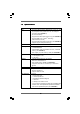
Contents 1 . Introduction ........................................................... 5 1.1 1.2 1.3 1.4 Package Contents ..................................................................... Specifications ............................................................................ Motherboard Layout ................................................................. I/O Panel .................................................................................... 5 6 11 12 2 . Installation ...................
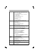
3.5 3.6 3.7 3.8 3.4.4 Storage Configuration .................................................... 3.4.5 PCIPnP Configuration ...................................................... 3.4.6 Floppy Configuration ...................................................... 3.4.7 Super IO Configuration ................................................... 3.4.8 USB Configuration .......................................................... Hardware Health Event Monitoring Screen ............................. Boot Screen ....
1. Introduction Thank you for purchasing ASRock N68-GE3 UCC motherboard, a reliable motherboard produced under ASRock’s consistently stringent quality control. It delivers excellent performance with robust design conforming to ASRock’s commitment to quality and endurance. In this manual, chapter 1 and 2 contain introduction of the motherboard and step-by-step guide to the hardware installation. Chapter 3 and 4 contain the configuration guide to BIOS setup and information of the Support CD.
1.2 Specifications Platform CPU Chipset Memory Expansion Slot Graphics Audio LAN Rear Panel I/O - Micro ATX Form Factor: 9.6-in x 8.2-in, 24.4 cm x 20.8 cm - Support for AM3 processors: AMD PhenomTM II X6 / X4 / X3 / X2 (except 920 / 940) / Athlon II X4 / X3 / X2 / Sempron processors (see CAUTION 1) - Six-Core CPU Ready - Supports UCC feature (Unlock CPU Core) (see CAUTION 2) - Supports AMD’s Cool ‘n’ QuietTM Technology - FSB 1000 MHz (2.
Connector BIOS Feature Support CD Unique Feature Hardware Monitor OS Certifications - 4 x Serial ATAII 3.0Gb/s connectors, support RAID (RAID 0, RAID 1, RAID 0+1, RAID 5, JBOD), NCQ and “Hot Plug” functions (see CAUTION 9) - 1 x ATA133 IDE connector (supports 2 x IDE devices) - 1 x Floppy connector - 1 x COM port header - CPU/Chassis/Power FAN connector - 24 pin ATX power connector - 4 pin 12V power connector - CD in header - Front panel audio header - 3 x USB 2.0 headers (support 6 USB 2.
* For detailed product information, please visit our website: http://www.asrock.com WARNING Please realize that there is a certain risk involved with overclocking, including adjusting the setting in the BIOS, applying Untied Overclocking Technology, or using the thirdparty overclocking tools. Overclocking may affect your system stability, or even cause damage to the components and devices of your system. It should be done at your own risk and expense.
10. It is a user-friendly ASRock overclocking tool which allows you to surveil your system by hardware monitor function and overclock your hardware devices to get the best system performance under Windows® environment. Please visit our website for the operation procedures of ASRock OC Tuner. ASRock website: http://www.asrock.com 11. Featuring an advanced proprietary hardware and software design, Intelligent Energy Saver is a revolutionary technology that delivers unparalleled power savings.
15. If you desire a faster, less restricted way of charging your Apple devices, such as iPhone/iPod/iPad Touch, ASRock has prepared a wonderful solution for you - ASRock APP Charger. Simply installing the APP Charger driver, it makes your iPhone charged much quickly from your computer and up to 40% faster than before.
1.3 Motherboard Layout 3 2 1 5 4 6 8 7 20.8cm (8.2-in) PS2 Mouse PS2_USB_PW1 1 1 CPU_FAN1 ATX12V1 Phenom II Center: REAR SPK Bottom: SPDIF_01 Center: FRONT Designed in Taipei LAN PHY Top: LINE IN Bottom: MIC IN 30 Top: SIDE SPK 32 31 N68-GE3 UCC NVIDIA GeForce 7025 / nForce 630a PCIE1 Super I/O PCI1 24.4cm (9.
1.4 I/O Panel 2 1 13 1 *2 3 4 5 6 ** 7 Parallel Port LAN RJ-45 Port Side Speaker (Gray) Rear Speaker (Black) Central / Bass (Orange) Line In (Light Blue) Front Speaker (Lime) 8 9 10 11 12 13 6 4 7 5 8 9 10 11 12 3 Microphone (Pink) USB 2.0 Ports (USB01) USB 2.0 Ports (USB23) VGA Port PS/2 Keyboard Port (Purple) PS/2 Mouse Port (Green) * There are two LED next to the LAN port. Please refer to the table below for the LAN port LED indications.
To enable Multi-Streaming function, you need to connect a front panel audio cable to the front panel audio header. After restarting your computer, you will find “VIA HD Audio Deck” tool on your system. Please follow below instructions according to the OS you install. For Windows® XP / XP 64-bit OS: Please click “VIA HD Audio Deck” icon. Click “Jack” and then click “Configuration”. In “Configuration” screen, please check the item “Independent Headphone”.
2. Installation This is a Micro ATX form factor (9.6-in x 8.2-in, 24.4 cm x 20.8 cm) motherboard. Before you install the motherboard, study the configuration of your chassis to ensure that the motherboard fits into it. Pre-installation Precautions Take note of the following precautions before you install motherboard components or change any motherboard settings. Before you install or remove any component, ensure that the power is switched off or the power cord is detached from the power supply.
2.1 CPU Installation Step 1. Step 2. Step 3. o Unlock the socket by lifting the lever up to a 90 angle. Position the CPU directly above the socket such that the CPU corner with the golden triangle matches the socket corner with a small triangle. Carefully insert the CPU into the socket until it fits in place. The CPU fits only in one correct orientation. DO NOT force the CPU into the socket to avoid bending of the pins. Step 4.
2.3 Installation of Memory Modules (DIMM) This motherboard provides four 240-pin DDR3 (Double Data Rate 3) DIMM slots, and supports Dual Channel Memory Technology. For dual channel configuration, you always need to install identical (the same brand, speed, size and chiptype) DDR3 DIMM pair in the slots of the same color. In other words, you have to install identical DDR3 DIMM pair in Dual Channel A (DDR3_A1 and DDR3_B1; Blue slots; see p.11 No.
Installing a DIMM Please make sure to disconnect power supply before adding or removing DIMMs or the system components. Step 1. Step 2. Unlock a DIMM slot by pressing the retaining clips outward. Align a DIMM on the slot such that the notch on the DIMM matches the break on the slot. notch break notch break The DIMM only fits in one correct orientation. It will cause permanent damage to the motherboard and the DIMM if you force the DIMM into the slot at incorrect orientation. Step 3.
2.4 Expansion Slots (PCI and PCI Express Slots) There are 2 PCI slots and 2 PCI Express slots on this motherboard. PCI slots: PCI slots are used to install expansion cards that have the 32-bit PCI interface. PCIE slots: PCIE1 (PCIE x1 slot) is used for PCI Express cards with x1 lane width cards, such as Gigabit LAN card, SATA2 card, etc. PCIE2 (PCIE x16 slot) is used for PCI Express cards with x16 lane width graphics cards. Installing an expansion card Step 1. Step 2. Step 3. Step 4.
2.5 Easy Multi Monitor Feature This motherboard supports Multi Monitor upgrade. With the internal onboard VGA and the external add-on PCI Express VGA card, you can easily enjoy the benefits of Multi Monitor feature. Please refer to the following steps to set up a multi monitor environment: 1. Install the NVIDIA® PCI Express VGA card to PCIE2 (PCIE x16 slot). Please refer to page 18 for proper expansion card installation procedures for details. 2.
B. Click the items “This is my main monitor” and “Extend the desktop onto this monitor”. C. Click “OK” to save your change. D. Repeat steps A through C for the display icon identified by the number one, two and three. 6. Use Multi Monitor feature. Click and drag the display icons to positions representing the physical setup of your monitors that you would like to use. The placement of display icons determines how you move items from one monitor to another.
2.6 Jumpers Setup The illustration shows how jumpers are setup. When the jumper cap is placed on pins, the jumper is “Short”. If no jumper cap is placed on pins, the jumper is “Open”. The illustration shows a 3-pin jumper whose pin1 and pin2 are “Short” when jumper cap is placed on these 2 pins. Jumper Setting PS2_USB_PW1 2_3 1_2 Short pin2, pin3 to enable +5VSB (standby) for PS/2 +5V +5VSB or USB23 wake up events.
2.7 Onboard Headers and Connectors Onboard headers and connectors are NOT jumpers. Do NOT place jumper caps over these headers and connectors. Placing jumper caps over the headers and connectors will cause permanent damage of the motherboard! • Floppy Connector (33-pin FLOPPY1) (see p.11 No. 24) Pin1 FLOPPY1 the red-striped side to Pin1 Note: Make sure the red-striped side of the cable is plugged into Pin1 side of the connector. Primary IDE connector (Blue) (39-pin IDE1, see p.11 No.
USB 2.0 Headers USB_PWR P-9 P+9 GND DUMMY (9-pin USB8_9) (see p.11 No. 17) 1 GND P+8 P-8 USB_PWR USB_PWR P-7 P+7 GND DUMMY (9-pin USB6_7) (see p.11 No. 18) Besides four default USB 2.0 ports on the I/O panel, there are three USB 2.0 headers on this motherboard. Each USB 2.0 header can support two USB 2.0 ports. 1 GND P+6 P-6 USB_PWR USB_PWR P-5 P+5 GND DUMMY (9-pin USB4_5) (see p.11 No. 19) 1 GND P+4 P-4 USB_PWR Internal Audio Connectors (4-pin CD1) CD1 (CD1: see p.11 No.
System Panel Header PLED+ PLEDPWRBTN# GND (9-pin PANEL1) (see p.11 No. 21) 1 This header accommodates several system front panel functions. DUMMY RESET# GND HDLEDHDLED+ Chassis Speaker Header (4-pin SPEAKER 1) (see p.11 No. 20) 1 SPEAKER DUMMY DUMMY +5V Chassis and Power Fan Connectors (3-pin CHA_FAN1) (see p.11 No. 22) GND +12V CHA_FAN_SPEED (3-pin PWR_FAN1) Please connect the chassis speaker to this header.
ATX 12V Power Connector Please note that it is necessary to connect a power supply with ATX 12V plug to this connector. Failing to do so will cause power up failure. (4-pin ATX12V1) (see p.11 No. 3) Serial port Header RRXD1 DDTR#1 DDSR#1 CCTS#1 (9-pin COM1) (see p.11 No. 25) 1 RRI#1 RRTS#1 GND TTXD1 DDCD#1 25 This COM1 header supports a serial port module.
2.8 SA SATTAII Hard Disk Setup Guide Before installing SATAII hard disk to your computer, please carefully read below SATAII hard disk setup guide. Some default setting of SATAII hard disks may not be at SATAII mode, which operate with the best performance. In order to enable SATAII function, please follow the below instruction with different vendors to correctly adjust your SATAII hard disk to SATAII mode in advance; otherwise, your SATAII hard disk may fail to run at SATAII mode.
2.9 Serial A ATTA (SA (SATTA) / Serial A ATTAII (SA (SATTAII) Hard Disks Installation This motherboard adopts NVIDIA® GeForce 7025 / nForce 630a chipset that supports Serial ATA (SATA) / Serial ATAII (SATAII) hard disks and RAID functions. You may install SATA / SATAII hard disks on this motherboard for internal storage devices. This section will guide you to install the SATA / SATAII hard disks. STEP 1: Install the SATA / SATAII hard disks into the drive bays of your chassis.
2.11 SA eature and Operation SATTA / SA SATTAII HDD Hot Plug FFeature Guide This motherboard supports Hot Plug feature for SATA / SATAII HDD in RAID mode. Please read below operation guide of SATA / SATAII HDD Hot Plug feature carefully. Before you process the SATA / SATAII HDD Hot Plug, please check below cable accessories from the motherboard gift box pack. A. 7-pin SATA data cable B. SATA power cable with SATA 15-pin power connector interface A. SATA data cable (Red) B.
How to Hot Plug a SATA / SATAII HDD: Points of attention, before you process the Hot Plug: Please do follow below instruction sequence to process the Hot Plug, improper procedure will cause the SATA / SATAII HDD damage and data loss. Step 1 Please connect SATA power cable 1x4-pin end Step 2 Connect SATA data cable to the motherboard’s SATAII connector. (White) to the power supply 1x4-pin cable.
2 . 1 2 Driver Installation Guide To install the drivers to your system, please insert the support CD to your optical drive first. Then, the drivers compatible to your system can be auto-detected and listed on the support CD driver page. Please follow the order from up to bottom side to install those required drivers. Therefore, the drivers you install can work properly. 2.
D. Then you will see these messages, Please insert a blank formatted diskette into floppy drive A: press any key to start Please insert a floppy diskette into the floppy drive, and press any key. E. The system will start to format the floppy diskette and copy SATA / SATAII drivers into the floppy diskette. STEP 3: Set Up BIOS. A. Enter BIOS SETUP UTILITY Advanced screen Storage Configuration. B. Set the “SATA Operation Mode” option to [RAID]. STEP 4: Use “RAID Installation Guide” to set RAID configuration.
2.14.2 Installing Windows ® 7 / 7 64-bit / Vista TM / Vista TM 64-bit With RAID Functions If you want to install Windows® 7 / 7 64-bit / VistaTM / VistaTM 64-bit on your SATA / SATAII HDDs with RAID functions, please follow below steps. STEP 1: Set Up BIOS. A. Enter BIOS SETUP UTILITY Advanced screen Storage Configuration. B. Set the “SATA Operation Mode” option to [RAID]. STEP 2: Use “RAID Installation Guide” to set RAID configuration.
3. BIOS SETUP UTILITY 3.1 Introduction This section explains how to use the BIOS SETUP UTILITY to configure your system. The SPI Memory on the motherboard stores the BIOS SETUP UTILITY. You may run the BIOS SETUP UTILITY when you start up the computer. Please press or during the Power-On-Self-Test (POST) to enter the BIOS SETUP UTILITY, otherwise, POST will continue with its test routines.
3 . 1 . 2 Navigation Keys Please check the following table for the function description of each navigation key. Navigation Key(s) / / + / 3.
3.3 OC TTweak weak er Screen weaker In the OC Tweaker screen, you can set up overclocking features. Main OC Tweaker BIOS SETUP UTILITY Advanced H/W Monitor Boot CPU Configuration [Auto] [200] [100] [Enabled] [3] [Enabled] [Enabled] [Enabled] [Disabled] [Disabled] Processor Maximum Frequency x15.0 3000 MHZ North Bridge Maximum Frequency x10.0 2000 MHZ Processor Maximum Voltage 1.
ASRock UCC UCC (Unlock CPU Core) feature simplifies AMD CPU activation. As long as a simple switch of the BIOS option “ASRock UCC”, you can unlock the extra CPU core to enjoy an instant performance boost. When UCC feature is enabled, the dual-core or triple-core CPU will boost to the quad-core CPU, and some CPU, including quad-core CPU, can also increase L3 cache size up to 6MB, which means you can enjoy the upgrade CPU performance with a better price.
NB Frequency Multiplier For safety and system stability, it is not recommended to adjust the value of this item. HT Bus Speed This feature allows you selecting Hyper-Transport bus speed. Configuration options: [Auto], [x1 200 MHz] to [x5 1000 MHz]. HT Bus Width This feature allows you selecting Hyper-Transport bus width. Configuration options: [Auto], [8 Bit] and [16 Bit]. Memory Configuration Memory Clock This item can be set by the code using [Auto].
Channel Interleaving This allows you to enable Channel Memory Interleaving. The default value is [Hash 2]. CAS Latency (CL) Use this item to adjust the means of memory accessing. Configuration options: [Auto], [4CLK] to [12CLK]. The default value is [Auto]. TRCD Use this to adjust TRCD values. Configuration options: [Auto], [5CLK] to [12CLK]. The default value is [Auto]. TRP Use this to adjust TRP values. Configuration options: [Auto], [5CLK] to [12CLK]. The default value is [Auto].
TRDRD Use this to adjust TRWTTD values. Configuration options: [Auto], [3CLK] to [10CLK]. The default value is [Auto]. TRFC0 Use this to adjust TRFC0 values. Configuration options: [Auto], [90ns], [110ns], [160ns], [300ns] and [350ns]. The default value is [Auto]. TRFC1 Use this to adjust TRFC1 values. Configuration options: [Auto], [90ns], [110ns], [160ns], [300ns] and [350ns]. The default value is [Auto]. MA Timing Use this to adjust values for MA timing. Configuration options: [Auto], [2T], [1T].
CHA CKE Drive Use this to adjust values for CHA CKE Drive. Configuration options: [Auto], [1.00x], [1.25x], [1.50x] and [2.00x]. The default value is [Auto]. CHA CS/ODT Drive Use this to adjust values for CHA CS/ODT Drive. Configuration options: [Auto], [1.00x], [1.25x], [1.50x] and [2.00x]. The default value is [Auto]. CHA ADDR/CMD Drive Use this to adjust values for CHA ADDR/CMD Drive. Configuration options: [Auto], [1.00x], [1.25x], [1.50x] and [2.00x]. The default value is [Auto].
Chipset Settings Chipset Voltage Use this to select chipset voltage. Configuration options: [Auto], [1.25V] to [1.40V]. The default value is [Auto]. Would you like to save current setting user defaults? In this option, you are allowed to load and save three user defaults according to your own requirements.
3.4 Advanced Screen In this section, you may set the configurations for the following items: CPU Configuration, Chipset Configuration, ACPI Configuration, Storage Configuration, PCIPnP Configuration, Floppy Configuration, SuperIO Configuration, and USB Configuration. Main BIOS SETUP UTILITY Boot OC Tweaker Advanced H/W Monitor Advanced Settings Security Exit Options for CPU WARNING : Setting wrong values in below sections may cause system to malfunction.
3.4.1 CPU Configuration BIOS SETUP UTILITY Advanced Enabling this function may reduce CPU voltage and memory freq., and lead to system stability or compatibility issue with some memory modules or power supplies. Please set this item to [Disabled] if above issue occurs. CPU Configuration Cool ‘n’ Quiet Secure Virtual Machine Enhanced Halt State L3 Cache Allocation [Auto] [Enabled] [Disabled] [Auto] +F1 F9 F10 ESC Select Screen Select Item Change Option General Help Load Defaults Save and Exit Exit v02.
3 . 4 . 2 Chipset Configuration BIOS SETUP UTILITY Advanced Chipset Settings Auto/Enable/Disable Onboard HD Audio. Onboard LAN Onboard HD Audio Front Panel Share Memory Primary Graphics Adapter [Auto] [Auto] [Enabled] [Auto] [PCI] CPU Thermal Throttle [Enabled] +F1 F9 F10 ESC Select Screen Select Item Change Option General Help Load Defaults Save and Exit Exit v02.54 (C) Copyright 1985-2003, American Megatrends, Inc. Onboard LAN This allows you to enable or disable the onboard LAN feature.
3.4.3 ACPI Configuration BIOS SETUP UTILITY Advanced ACPI Settings Suspend To RAM Check Ready Bit Away Mode Support [Auto] [Enabled] [Disabled] Restore on AC / Power Loss Ring-In Power On PCI Devices Power On PS / 2 Keyboard Power On RTC Alarm Power On [Power Off] [Disabled] [Disabled] [Disabled] [Disabled] ACPI HPET Table OSC Control [Disabled] [Auto] Select auto-detect or disable the STR feature.
ACPI HPET Table Use this item to enable or disable ACPI HPET Table. The default value is [Disabled]. Please set this option to [Enabled] if you plan to use this motherboard to submit Windows® VistaTM certification. OSC Control Use this item to enable or disable OSC control. Configuration options: [Auto], [Enabled] and [Disabled]. The default value is [Auto].
3.4.4 Storage Configuration BIOS SETUP UTILITY Advanced Options Storage Configuration Onboard IDE Controller Onboard SATA Controller SATA Operation Mode Disabled Enabled [Enabled] [Enabled] [IDE] [Hard Disk] [Not Detected] [Not Detected] [Not Detected] [Not Detected] [Not Detected] IDE1 Master IDE1 Slave SATAII_1 SATAII_2 SATAII_3 SATAII_4 +F1 F9 F10 ESC Select Screen Select Item Change Option General Help Load Defaults Save and Exit Exit v02.54 (C) Copyright 1985-2003, American Megatrends, Inc.
TYPE Use this item to configure the type of the IDE device that you specify. Configuration options: [Not Installed], [Auto], [CD/DVD], and [ARMD]. [Not Installed]: Select [Not Installed] to disable the use of IDE device. [Auto]: Select [Auto] to automatically detect the hard disk drive. After selecting the hard disk information into BIOS, use a disk utility, such as FDISK, to partition and format the new IDE hard disk drives. This is necessary so that you can write or read data from the hard disk.
3.4.5 PCIPnP Configuration BIOS SETUP UTILITY Advanced Value in units of PCI clocks for PCI device latency timer register. Advanced PCI / PnP Settings PCI Latency Timer PCI IDE BusMaster [32] [Enabled] +F1 F9 F10 ESC Select Screen Select Item Change Option General Help Load Defaults Save and Exit Exit v02.54 (C) Copyright 1985-2003, American Megatrends, Inc. Setting wrong values in this section may cause the system to malfunction. PCI Latency Timer The default value is 32.
3.4.6 Floppy Configuration In this section, you may configure the type of your floppy drive. BIOS SETUP UTILITY Advanced Floppy Configuration [1.44 MB 31 2"] Floppy A Select the type of floppy drive connected to the system. +F1 F9 F10 ESC Select Screen Select Item Change Option General Help Load Defaults Save and Exit Exit v02.54 (C) Copyright 1985-2003, American Megatrends, Inc. 3 . 4 .
Parallel Port Mode Use this item to set the operation mode of the parallel port. The default value is [ECP+EPP]. If this option is set to [ECP+EPP], it will show the EPP version in the following item, “EPP Version”. Configuration options: [Normal], [Bi-Directional], and [ECP+EPP]. EPP Version Use this item to set the EPP version. Configuration options: [1.9] and [1.7]. ECP Mode DMA Channel Use this item to set the ECP mode DMA channel. Configuration options: [DMA0], [DMA1], and [DMA3].
3 . 4 . 8 USB Configuration BIOS SETUP UTILITY Advanced USB Configuration USB Controller USB 2.0 Support Legacy USB Support [Enabled] [Enabled] [Enabled] USB Keyboard/Remote Power On USB Mouse Power On [Disabled] [Disabled] To enable or disable the onboard USB controllers. +F1 F9 F10 ESC Select Screen Select Item Change Option General Help Load Defaults Save and Exit Exit v02.54 (C) Copyright 1985-2003, American Megatrends, Inc.
3.5 Hardware Health Event Monitoring Screen In this section, it allows you to monitor the status of the hardware on your system, including the parameters of the CPU temperature, motherboard temperature, CPU fan speed, chassis fan speed, and the critical voltage. Main OC Tweaker BIOS SETUP UTILITY Boot Advanced H/W Monitor Hardware Health Event Monitoring CPU Temperature M / B Temperature : 37 C / 98 F : 27 C / 80 F CPU Fan Speed Chassis Fan1 Speed Power Fan Speed : 4722 RPM : N/A : N/A Vcore + 3.
3.6 Boot Screen In this section, it will display the available devices on your system for you to configure the boot settings and the boot priority. Main OC Tweaker BIOS SETUP UTILITY Advanced H/W Monitor Boot Boot Settings Exit Configure Settings during System Boot.
3.7 Security Screen In this section, you may set or change the supervisor/user password for the system. For the user password, you may also clear it. Main OC Tweaker BIOS SETUP UTILITY Advanced H/W Monitor Boot Security Settings Supervisor Password User Password Security Exit Install or Change the password. : Not Installed : Not Installed Change Supervisor Password Change User Password Enter F1 F9 F10 ESC Select Screen Select Item Change General Help Load Defaults Save and Exit Exit v02.
3 . 8 Exit Screen Main OC Tweaker BIOS SETUP UTILITY Advanced H/W Monitor Boot Exit Options Exit system setup after saving the changes. Save Changes and Exit Discard Changes and Exit Discard Changes Load Load Load Load Security Exit F10 key can be used for this operation. BIOS Defaults Performance Setup Default (IDE/SATA) Performance Setup RAID Mode Power Saving Setup Default Enter F1 F9 F10 ESC Select Screen Select Item Go to Sub Screen General Help Load Defaults Save and Exit Exit v02.
Supportt 4. Sof tware Suppor 4.1 Install Operating System This motherboard supports various Microsoft® Windows® operating systems: 7 / 7 64-bit / VistaTM / VistaTM 64-bit / XP / XP 64-bit. Because motherboard settings and hardware options vary, use the setup procedures in this chapter for general reference only. Refer to your OS documentation for more information. 4.