NF6-GLAN User Manual Version 1.2 Published May 2009 Copyright©2009 ASRock INC. All rights reserved.
Copyright Notice: No part of this manual may be reproduced, transcribed, transmitted, or translated in any language, in any form or by any means, except duplication of documentation by the purchaser for backup purpose, without written consent of ASRock Inc. Products and corporate names appearing in this manual may or may not be registered trademarks or copyrights of their respective companies, and are used only for identification or explanation and to the owners’ benefit, without intent to infringe.
Contents 1 . Introduction ............................................................ 5 1.1 1.2 1.3 1.4 Package Contents ..................................................................... Specifications ............................................................................ Motherboard Layout ................................................................... ASRock HD 6CH I/O .................................................................. 5 6 10 11 2 . Installation ..........................
3.4 3.5 3.6 3.7 3.3.5 PCIPnP Configuration ...................................................... 3.3.6 Floppy Configuration ...................................................... 3.3.7 Super IO Configuration ................................................... 3.3.8 USB Configuration .......................................................... Hardware Health Event Monitoring Screen ............................. Boot Screen .............................................................................. 3.5.
1. Introduction Thank you for purchasing ASRock NF6-GLAN motherboard, a reliable motherboard produced under ASRock’s consistently stringent quality control. It delivers excellent performance with robust design conforming to ASRock’s commitment to quality and endurance. In this manual, chapter 1 and 2 contain introduction of the motherboard and step-bystep guide to the hardware installation. Chapter 3 and 4 contain the configuration guide to BIOS setup and information of the Support CD.
1.2 Specifications Platform CPU Chipset Memory Expansion Slot Audio LAN Rear Panel I/O Connector - ATX Form Factor: 12.0-in x 8.0-in, 30.5 cm x 20.3 cm - Support for Socket AM2+ / AM2 processors: AMD PhenomTM FX / Phenom / Athlon 64 FX / Athlon 64 X2 Dual-Core / Athlon X2 Dual-Core / Athlon 64 / Sempron processor - Support for AM3 processors: AMD PhenomTM II X4 / X3 and Athlon II X4 / X3 / X2 processors - Supports AMD’s Cool ‘n’ QuietTM Technology - FSB 1000 MHz (2.
BIOS Feature Support CD Unique Feature Hardware Monitor OS Certifications - 1 x HDMI_SPDIF header - CPU/Chassis FAN connector - 24 pin ATX power connector - 4 pin 12V power connector - CD in header - Front panel audio connector - 2 x USB 2.0 headers (support 3 USB 2.0 ports) (see CAUTION 6) - 1 x WiFi header (see CAUTION 7) - 4Mb AMI BIOS - AMI Legal BIOS - Supports “Plug and Play” - ACPI 1.1 Compliance Wake Up Events - Supports jumperfree - SMBIOS 2.3.
CAUTION! 1. This motherboard supports Untied Overclocking Technology. Please read “Untied Overclocking Technology” on page 30 for details. 2. This motherboard supports Dual Channel Memory Technology. Before you implement Dual Channel Memory Technology, make sure to read the installation guide of memory modules on page 14 for proper installation. 3. Whether 1066MHz memory speed is supported depends on the AM2+ CPU you adopt.
10. While CPU overheat is detected, the system will automatically shutdown. Before you resume the system, please check if the CPU fan on the motherboard functions properly and unplug the power cord, then plug it back again. To improve heat dissipation, remember to spray thermal grease between the CPU and the heatsink when you install the PC system. 11. This motherboard supports ASRock AM2 Boost overclocking technology.
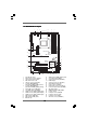
1.3 Motherboard Layout 1 4 5 3 2 7 6 20.3cm (8.0-in) PS2_USB_PW1 Center: FRONT Top: LINE IN Bottom: MIC IN DDR2 800 ATXPWR1 30.5cm (12.0-in) FSB800 DDRII_3 (64 bit, 240-pin module) Top: RJ-45 USB 2.0 T: USB4 B: USB5 31 FSB800 SOCKET AM2 USB 2.0 T: USB0 B: USB1 DDRII_2 (64 bit, 240-pin module) COM1 PARALLEL PORT PS2 Keyboard USB 2.
1.4 ASRock HD 6CH I/O 1 2 3 4 5 11 1 2 3 4 5 6 10 9 8 Parallel Port RJ-45 Port Line In (Light Blue) Line Out (Lime) Microphone (Pink) USB 2.0 Ports (USB45) 7 8 9 10 11 7 6 USB 2.0 Ports (USB01) USB 2.0 Ports (USB23) COM Port PS/2 Keyboard Port (Purple) PS/2 Mouse Port (Green) * To enable Multi-Streaming function, you need to connect a front panel audio cable to the front panel audio header. Please refer to below steps for the software setting of Multi-Streaming.
2. Installation This is an ATX form factor (12.0-in x 8.0-in, 30.5 cm x 20.3 cm) motherboard. Before you install the motherboard, study the configuration of your chassis to ensure that the motherboard fits into it. Pre-installation Precautions Take note of the following precautions before you install motherboard components or change any motherboard settings. Before you install or remove any component, ensure that the power is switched off or the power cord is detached from the power supply.
2.1 CPU Installation Step 1. Step 2. Step 3. o Unlock the socket by lifting the lever up to a 90 angle. Position the CPU directly above the socket such that the CPU corner with the golden triangle matches the socket corner with a small triangle. Carefully insert the CPU into the socket until it fits in place. The CPU fits only in one correct orientation. DO NOT force the CPU into the socket to avoid bending of the pins. Step 4.
2.3 Installation of Memory Modules (DIMM) This motherboard provides four 240-pin DDR2 (Double Data Rate 2) DIMM slots, and supports Dual Channel Memory Technology. For dual channel configuration, you always need to install identical (the same brand, speed, size and chiptype) DDR2 DIMM pair in the slots of the same color. In other words, you have to install identical DDR2 DIMM pair in Dual Channel A (DDRII_1 and DDRII_2; Yellow slots; see p.10 No.
Installing a DIMM Please make sure to disconnect power supply before adding or removing DIMMs or the system components. Step 1. Step 2. Unlock a DIMM slot by pressing the retaining clips outward. Align a DIMM on the slot such that the notch on the DIMM matches the break on the slot. notch break notch break The DIMM only fits in one correct orientation. It will cause permanent damage to the motherboard and the DIMM if you force the DIMM into the slot at incorrect orientation. Step 3.
2.4 Expansion Slots (PCI and PCI Express Slots) There are 3 PCI slots and 3 PCI Express slots on this motherboard. PCI slots: PCI slots are used to install expansion cards that have the 32-bit PCI interface. PCIE slots: PCIE1 (PCIE x1 slot) is used for PCI Express cards with x1 lane width cards, such as Gigabit LAN card, SATA2 card, etc. PCIE2 (PCIE x16 slot) is used for PCI Express cards with x16 lane width graphics cards.
2.5 Jumpers Setup The illustration shows how jumpers are setup. When the jumper cap is placed on pins, the jumper is “Short”. If no jumper cap is placed on pins, the jumper is “Open”. The illustration shows a 3-pin jumper whose pin1 and pin2 are “Short” when jumper cap is placed on these 2 pins. Jumper PS2_USB_PW1 Setting Short pin2, pin3 to enable +5VSB (standby) for PS/2 or +5V +5VSB USB wake up events. Note: To select +5VSB, it requires 2 Amp and higher standby current provided by power supply.
2.6 Onboard Headers and Connectors Onboard headers and connectors are NOT jumpers. Do NOT place jumper caps over these headers and connectors. Placing jumper caps over the headers and connectors will cause permanent damage of the motherboard! • Floppy Connector (33-pin FLOPPY1) (see p.10 No. 22) Pin1 FLOPPY1 the red-striped side to Pin1 Note: Make sure the red-striped side of the cable is plugged into Pin1 side of the connector. Primary IDE connector (Blue) (39-pin IDE1, see p.10 No.
Serial ATA (SATA) Power Cable (Optional) connect to the SATA HDD power connector connect to the power supply USB 2.0 Headers USB_PWR P-7 P+7 GND DUMMY (9-pin USB6_7) (see p.10 No. 14) 1 GND P+6 P-6 USB_PWR (4-pin USB8) 1 Please connect the black end of SATA power cable to the power connector on each drive. Then connect the white end of SATA power cable to the power connector of the power supply. Besides six default USB 2.0 ports on the I/O panel, there are two USB 2.0 headers on this motherboard.
Front Panel Audio Header GND PRESENCE# MIC_RET OUT_RET (9-pin HD_AUDIO1) (see p.10, No. 24) 1 OUT2_L J_SENSE OUT2_R MIC2_R MIC2_L This is an interface for the front panel audio cable that allows convenient connection and control of audio devices. 1. High Definition Audio supports Jack Sensing, but the panel wire on the chassis must support HDA to function correctly. Please follow the instruction in our manual and chassis manual to install your system. 2.
Chassis Speaker Header (4-pin SPEAKER 1) (see p.10 No. 18) 1 SPEAKER DUMMY DUMMY +5V Chassis Fan Connector Please connect a chassis fan (3-pin CHA_FAN1) GND +12V CHA_FAN_SPEED (see p.10 No. 20) CPU Fan Connector (4-pin CPU_FAN1) Please connect the chassis speaker to this header. +12V CPU_FAN_SPEED GND FAN_SPEED_CONTROL (see p.10 No. 5) 1 2 3 4 cable to this connector and match the black wire to the ground pin.
HDMI_SPDIF Header HDMI_SPDIF header, providing SPDIF audio output to HDMI VGA card, allows the system to connect HDMI Digital TV/ projector/LCD devices. Please connect the HDMI_SPDIF connector of HDMI VGA card to this header. 1 (3-pin HDMI_SPDIF1) (see p.10 No. 26) +5V HDMI_SPDIF Cable GND SPDIFOUT Please connect the black end (A) of HDMI_SPDIF cable to the HDMI_SPDIF header on the motherboard. Then connect the white end (B or C) of HDMI_SPDIF cable to the HDMI_SPDIF connector of HDMI VGA card.
2.7 HDMI_SPDIF Header Connection Guide HDMI (High-Definition Multi-media Interface) is an all-digital audio/video specification, which provides an interface between any compatible digital audio/video source, such as a set-top box, DVD player, A/V receiver and a compatible digital audio or video monitor, such as a digital television (DTV). A complete HDMI system requires a HDMI VGA card and a HDMI ready motherboard with a HDMI_SPDIF header.
2.8 SA SATTAII Hard Disk Setup Guide Before installing SATAII hard disk to your computer, please carefully read below SATAII hard disk setup guide. Some default setting of SATAII hard disks may not be at SATAII mode, which operate with the best performance. In order to enable SATAII function, please follow the below instruction with different vendors to correctly adjust your SATAII hard disk to SATAII mode in advance; otherwise, your SATAII hard disk may fail to run at SATAII mode.
2.9 Serial A ATTA (SA (SATTA) / Serial A ATTAII (SA (SATTAII) Hard Disks Installation This motherboard adopts NVIDIA® GeForce 6150SE / nForce 430 or GeForce 7025 / nForce 630a chipset that supports Serial ATA (SATA) / Serial ATAII (SATAII) hard disks and RAID functions. You may install SATA / SATAII hard disks on this motherboard for internal storage devices. This section will guide you to install the SATA / SATAII hard disks.
2.11 SA eature and Operation SATTA / SA SATTAII HDD Hot Plug FFeature Guide This motherboard supports Hot Plug feature for SATA / SATAII HDD. Please read below operation guide of SATA / SATAII HDD Hot Plug feature carefully. Before you process the SATA / SATAII HDD Hot Plug, please check below cable accessories from the motherboard gift box pack. A. 7-pin SATA data cable B. SATA power cable with SATA 15-pin power connector interface A. SATA data cable (Red) B.
How to Hot Plug a SATA / SATAII HDD: Points of attention, before you process the Hot Plug: Please do follow below instruction sequence to process the Hot Plug, improper procedure will cause the SATA / SATAII HDD damage and data loss. Step 1 Please connect SATA power cable 1x4-pin end Step 2 Connect SATA data cable to the motherboard’s SATAII connector. (White) to the power supply 1x4-pin cable.
2.12 Driver Installation Guide To install the drivers to your system, please insert the support CD to your optical drive first. Then, the drivers compatible to your system can be auto-detected and listed on the support CD driver page. Please follow the order from up to bottom side to install those required drivers. Therefore, the drivers you install can work properly. 2.
D. Then you will see these messages, Please insert a blank formatted diskette into floppy drive A: press any key to start Please insert a floppy diskette into the floppy drive, and press any key. E. The system will start to format the floppy diskette and copy SATA / SATAII drivers into the floppy diskette. STEP 2: Set Up BIOS. A. Enter BIOS SETUP UTILITY Advanced screen IDE Configuration. B. Set the “SATA Operation Mode” option to [RAID]. STEP 3: Use “RAID Installation Guide” to set RAID configuration.
STEP 2: Use “RAID Installation Guide” to set RAID configuration. Before you start to configure RAID function, you need to check the RAID installation guide in the Support CD for proper configuration. Please refer to the BIOS RAID installation guide part of the document in the following path in the Support CD: .. \ RAID Installation Guide STEP 3: Install Windows® VistaTM / Windows® VistaTM 64-bit OS on your system.
3. BIOS SETUP UTILITY 3.1 Introduction This section explains how to use the BIOS SETUP UTILITY to configure your system. The Flash Memory on the motherboard stores the BIOS SETUP UTILITY. You may run the BIOS SETUP UTILITY when you start up the computer. Please press during the Power-On-Self-Test (POST) to enter the BIOS SETUP UTILITY, otherwise, POST will continue with its test routines.
3.1.2 Navigation Keys Please check the following table for the function description of each navigation key. Navigation Key(s) / / + / 3.
3.3 Advanced Screen In this section, you may set the configurations for the following items: CPU Configuration, Chipset Configuration, ACPI Configuration, IDE Configuration, PCIPnP Configuration, Floppy Configuration, SuperIO Configuration, and USB Configuration. Main Advanced BIOS SETUP UTILITY H/W Monitor Boot Security Exit Options for CPU Advanced Settings WARNING : Setting wrong values in below sections may cause system to malfunction.
Overclock Mode Use this to select Overclock Mode. The default value is [Auto]. Configuration options: [Auto], [CPU, PCIE, Sync.] and [CPU, PCIE, Async.]. CPU Frequency (MHz) Use this option to adjust CPU frequency. PCIE Frequency (MHz) Use this option to adjust PCIE frequency. CPU/LDT Spread Spectrum This feature will be set to [Enabled] as default. Configuration options: [Disabled] and [Enabled]. PCIE Spread Spectrum This feature will be set to [Enabled] as default.
Processor Maximum Voltage It will display Processor Maximum Voltage for reference. Multiplier/Voltage Change This item is set to [Auto] by default. If it is set to [Manual], you may adjust the value of Processor Frequency and Processor Voltage. However, it is recommended to keep the default value for system stability. BIOS SETUP UTILITY Advanced CPU Configuration If AUTO, multiplier and voltage will be left at the rated frequency/voltage.
CPU Frequency Multiplier This option appears only when you adopt Phenom CPU. However, for safety and system stability, it is not recommended to adjust the value of this item. CPU Frequency Divider This option appears only when you adopt Phenom CPU. However, for safety and system stability, it is not recommended to adjust the value of this item. CPU Voltage This option appears only when you adopt Phenom CPU. It allows you to adjust the value of CPU voltage.
TRTP Use this to adjust TRTP values. Configuration options: [Auto], [2-4CLK] and [3-5CLK]. The default value is [Auto]. TRAS Use this to adjust TRAS values. Configuration options: [Auto], [5CLK] to [18CLK]. The default value is [Auto]. TRRD Use this to adjust TRRD values. Configuration options: [Auto], [2CLK], [3CLK], [4CLK] and [5CLK]. The default value is [Auto]. TRC Use this to adjust TRC values. Configuration options: [11CLK] to [26CLK]. The default value is [Auto]. TWR Use this to adjust TWR values.
3 . 3 . 2 Chipset Configuration BIOS SETUP UTILITY Advanced Chipset Settings To set DRAM Voltage. Onboard LAN Onboard HD Audio Front Panel Primary Graphics Adapter [Enabled] [Auto] [Auto] [PCI] CPU-NB Link Speed CPU-NB Link Width [Auto] [Auto] DRAM Voltage Chipset Core Voltage [Auto] [Auto] +F1 F9 F10 ESC Select Screen Select Item Change Option General Help Load Defaults Save and Exit Exit v02.54 (C) Copyright 1985-2003, American Megatrends, Inc.
3 . 3 . 3 ACPI Configuration BIOS SETUP UTILITY Advanced ACPI Settings Suspend To RAM Repost Video on STR Resume Away Mode Support [Auto] [No] [Disabled] Restore on AC / Power Loss Ring-In Power On PCI Devices Power On PS / 2 Keyboard Power On RTC Alarm Power On [Power Off] [Disabled] [Disabled] [Disabled] [Disabled] ACPI HPET Table OSC Control [Disabled] [Auto] Select auto-detect or disable the STR feature.
ACPI HPET Table Use this item to enable or disable ACPI HPET Table. The default value is [Disabled]. Please set this option to [Enabled] if you plan to use this motherboard to submit Windows® VistaTM certification. OSC Control Use this option to adjust OSC control. The default value is [Auto]. Configuration options: [Auto], [Enabled] and [Disabled]. 3.3.4 IDE Configuration BIOS SETUP UTILITY Advanced ENABLED: enables the integrated IDE Controller. DISABLED: disables the integrated IDE Controller.
BIOS SETUP UTILITY Advanced IDE Master Device Vendor Size LBA Mode Block Mode PIO Mode Async DMA Ultra DMA S.M.A.R.T. Select the type of device connected to the system. :Hard Disk :MAXTOR 6L080J4 :80.0 GB :Supported :16Sectors :4 :MultiWord DMA-2 :Ultra DMA-6 :Supported Type LBA/Large Mode Block (Multi-Sector Transfer) PIO Mode DMA Mode S.M.A.R.T.
S.M.A.R.T. Use this item to enable or disable the S.M.A.R.T. (Self-Monitoring, Analysis, and Reporting Technology) feature. Configuration options: [Disabled], [Auto], [Enabled]. 32Bit Data Transfer Use this item to enable 32-bit access to maximize the IDE hard disk data transfer rate. 3.3.5 PCIPnP Configuration BIOS SETUP UTILITY Advanced Value in units of PCI clocks for PCI device latency timer register.
3.3.6 Floppy Configuration In this section, you may configure the type of your floppy drive. BIOS SETUP UTILITY Advanced Floppy Configuration [1.44 MB 31 2"] Floppy A Select the type of floppy drive connected to the system. +F1 F9 F10 ESC Select Screen Select Item Change Option General Help Load Defaults Save and Exit Exit v02.54 (C) Copyright 1985-2003, American Megatrends, Inc. 3.3.
Parallel Port Address Use this item to set the address for the onboard parallel port or disable it. Configuration options: [Disabled], [378], and [278]. Parallel Port Mode Use this item to set the operation mode of the parallel port. The default value is [ECP+EPP]. If this option is set to [ECP+EPP], it will show the EPP version in the following item, “EPP Version”. Configuration options: [Normal], [Bi-Directional], and [ECP+EPP]. EPP Version Use this item to set the EPP version. Configuration options: [1.
[Enabled] - Enables support for legacy USB. [Auto] - Enables legacy support if USB devices are connected. [Disabled] - USB devices are not allowed to use under legacy OS and BIOS setup when [Disabled] is selected. If you have USB compatibility issue, it is recommended to select [Disabled] to enter OS. [BIOS Setup Only] - USB devices are allowed to use only under BIOS setup and Windows / Linux OS. 3.
3.5 Boot Screen In this section, it will display the available devices on your system for you to configure the boot settings and the boot priority. Main Advanced BIOS SETUP UTILITY H/W Monitor Boot Boot Settings Exit Configure Settings during System Boot.
3.6 Security Screen In this section, you may set or change the supervisor/user password for the system. For the user password, you may also clear it. Main Advanced BIOS SETUP UTILITY H/W Monitor Boot Security Settings Supervisor Password User Password Security Exit Install or Change the password. : Not Installed : Not Installed Change Supervisor Password Change User Password Enter F1 F9 F10 ESC Select Screen Select Item Change General Help Load Defaults Save and Exit Exit v02.
3.7 Exit Screen Main Advanced BIOS SETUP UTILITY H/W Monitro Boot Exit Options Security Exit Exit system setup after saving the changes. Save Changes and Exit Discard Changes and Exit Discard Changes F10 key can be used for this operation. Load Optimal Defaults Enter F1 F9 F10 ESC Select Screen Select Item Go to Sub Screen General Help Load Defaults Save and Exit Exit v02.54 (C) Copyright 1985-2003, American Megatrends, Inc.
Supportt 4. Sof tware Suppor 4.1 Install Operating System This motherboard supports various Microsoft® Windows® operating systems: 2000 / XP / XP 64-bit / VistaTM / VistaTM 64-bit. Because motherboard settings and hardware options vary, use the setup procedures in this chapter for general reference only. Refer to your OS documentation for more information. 4.