Version 1.0 Published April 2014 Copyright©2014 ASRock INC. All rights reserved. Copyright Notice: No part of this documentation may be reproduced, transcribed, transmitted, or translated in any language, in any form or by any means, except duplication of documentation by the purchaser for backup purpose, without written consent of ASRock Inc.
The terms HDMI™ and HDMI High-Definition Multimedia Interface, and the HDMI logo are trademarks or registered trademarks of HDMI Licensing LLC in the United States and other countries. Manufactured under license under U.S. Patent Nos: 5,956,674; 5,974,380; 6,487,535; 7,003,467 & other U.S. and worldwide patents issued & pending. DTS, the Symbol, & DTS and the Symbol together is a registered trademark & DTS Connect, DTS Interactive, DTS Neo:PC are trademarks of DTS, Inc. Product includes software.
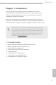
Contents Chapter 1 Introduction 1 1.1 Package Contents 1 1.2 Specifications 2 1.3 Unique Features 7 1.4 Motherboard Layout 11 1.5 I/O Panel 14 1.6 WiFi-802.11ac Module and ASRock WiFi 2.4/5 GHz Antenna 16 Chapter 2 Installation 17 2.1 Installing the CPU 18 2.2 Installing the CPU Fan and Heatsink 21 2.3 Installing Memory Modules (DIMM) 22 2.4 Expansion Slots (PCI Express Slots) 24 2.5 Jumpers Setup 25 2.6 Onboard Headers and Connectors 26 2.
3.6 ASRock APP Shop 62 3.6.1 UI Overview 62 3.6.2 Apps 63 3.6.3 BIOS & Drivers 66 3.6.4 Setting 67 3.7 68 Start8 Chapter 4 UEFI SETUP UTILITY 71 4.1 Introduction 71 4.1.1 UEFI Menu Bar 71 4.1.2 Navigation Keys 72 4.2 Main Screen 73 4.3 OC Tweaker Screen 74 4.4 Advanced Screen 83 4.4.1 CPU Configuration 84 4.4.2 Chipset Configuration 86 4.4.3 Storage Configuration 88 4.4.4 Intel® Rapid Start Technology 90 4.4.5 Intel® Smart Connect Technology 91 4.4.
4.7 Boot Screen 102 4.8 Security Screen 105 4.
Z97E-ITX/ac Chapter 1 Introduction Thank you for purchasing ASRock Z97E-ITX/ac motherboard, a reliable motherboard produced under ASRock’s consistently stringent quality control. It delivers excellent performance with robust design conforming to ASRock’s commitment to quality and endurance. In this manual, Chapter 1 and 2 contains the introduction of the motherboard and step-by-step installation guides. Chapter 3 contains the operation guide of the software and utilities.
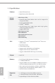
1.2 Specifications Platform Unique Feature English 2 • Mini-ITX Form Factor • High Density Glass Fabric PCB ASRock Super Alloy • Premium Alloy Choke (Reduces 70% core loss compared to iron powder choke) • Dual-Stack MOSFET (DSM) TM • NexFET MOSFET • 12K Plat i nu m C aps (10 0% Japa n made h ig h qu a l it y conductive polymer capacitors) • Sapphire Black PCB ASRock 802.
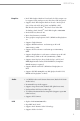
Graphics • Intel® HD Graphics Built-in Visuals and the VGA outputs can be supported only with processors which are GPU integrated. • Supports Intel® HD Graphics Built-in Visuals : Intel® Quick Sync Video with AVC, MVC (S3D) and MPEG-2 Full HW Encode1, Intel® InTruTM 3D, Intel® Clear Video HD Technology, Intel® InsiderTM, Intel® HD Graphics 4400/4600 • Pixel Shader 5.0, DirectX 11.1 • Max. shared memory 1792MB • Three graphics output options: DVI-I, HDMI and DisplayPort 1.
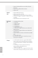
• Supports Lightning/ESD Protection (ASRock Full Spike Protection) • Supports Energy Efficient Ethernet 802.3az • Supports PXE Supports IEEE 802.11a/b/g/n/ac Supports Dual-Band (2.4/5 GHz) Supports High speed wireless connection up to 867Mbps 2 antennas to support 2 (Transmit) x 2 (Receive) diversity technology • Supports Bluetooth 4.0 / 3.
Z97E-ITX/ac • • • • • • 1 x Chassis Intrusion Header BIOS Feature • • • • 64Mb AMI UEFI Legal BIOS with multilingual GUI support ACPI 1.1 Compliant wake up events SMBIOS 2.3.1 support CPU, DRAM, PCH 1.05V, PCH 1.5V Voltage multi-adjustment Support CD • Drivers, Utilities, AntiVirus Software (Trial Version), Google Chrome Browser and Toolbar, Start8 (30 days trial), Kloudian Orbweb.ME Professional (Win 8.
Please realize that there is a certain risk involved with overclocking, including adjusting the setting in the BIOS, applying Untied Overclocking Technology, or using thirdparty overclocking tools. Overclocking may affect your system’s stability, or even cause damage to the components and devices of your system. It should be done at your own risk and expense. We are not responsible for possible damage caused by overclocking.
Z97E-ITX/ac 1.3 Unique Features ASRock Super Alloy This motherboard is specially designed with Super Alloy Technology for faster, stabler, and more durable performance, including Premium Alloy Choke, Dual-Stack MOSFET (DSM), NexFET TM MOSFET, 12K Platinum Cap, and Sapphire Black PCB. ASRock 802.11ac WiFi No one has time for weak WiFi signals and sluggish Internet connection! That’s why this motherboard comes with an exclusive 2T2R 802.
ASRock A-Tuning A-Tuning is ASRock’s multi purpose software suite with a new interface, more new features and improved utilities. ASRock Disk Health Report Displaying detailed HDD information. You can check the model names, capacities, temperatures, SMART info, health status, and other information of your HDDs here.
Z97E-ITX/ac ASRock Restart to UEFI Windows® 8 brings the ultimate boot up experience. The lightning boot up speed makes it hard to access the UEFI setup. ASRock Restart to UEFI allows users to enter the UEFI automatically when turning on the PC. By enabling this function, the PC will enter the UEFI directly after you restart. ASRock Full HD UEFI All new Full HD UEFI with a resolution of 1920 x 1080. The UEFI should be designed easy to use and setup.
ASRock Crashless BIOS ASRock Crashless BIOS allows users to update their BIOS without fear of failing. If power loss occurs during the BIOS updating process, ASRock Crashless BIOS will automatically finish the BIOS update procedure after regaining power. Please note that BIOS files need to be placed in the root directory of your USB disk. Only USB 2.0 ports support this feature.
Z97E-ITX/ac CPU_FAN1 RoHS USB3_5_6 SPEAKER1 1 CLRMOS1 1 1 1 PANEL1 PCIE1 English Center: FRONT Top: LINE IN Bottom: MIC IN 1 CI1 1 PLED PWRBTN MPCIE1 SATA3_3 Top: CTR BASS Bottom: Optical SPDIF Center: REAR SPK AUDIO CODEC HDLED RESET WiFi-802.11ac Module HD_AUDIO1 SATA3_4_5 Intel Z97 SATA3_1 USB_3_4 1 SATA3_0 USB_5_6 1 Top: RJ-45 SATA3_2 USB 3.0 T: USB3 B: USB4 64Mb BIOS TPMS1 HDMI_IN CHA_FAN1 ATXPWR1 CLRCBTN1 USB 3.
M2 English 12
Z97E-ITX/ac 1 CPU Fan Connector (CPU_FAN1) 2 ATX 12V Power Connector (ATX12V1) 3 2 x 240-pin DDR3 DIMM Slots (DDR3_A1, DDR3_B1) 4 ATX Power Connector (ATXPWR1) 5 Chassis Fan Connector (CHA_FAN1) 6 USB 3.
1.5 I/O Panel English 14 1 2 3 17 16 15 14 4 5 6 7 8 9 13 12 11 10 No. Description No. Description 1 USB 2.0 Ports (USB_1_2) 10 Microphone (Pink) 2 Antenna Ports 11 Optical SPDIF Out Port 3 DisplayPort 1.2 12 USB 3.0 Ports (USB3_3_4) 4 USB 3.
Z97E-ITX/ac * There are two LEDs on each LAN port. Please refer to the table below for the LAN port LED indications. ACT/LINK LED SPEED LED LAN Port Activity / Link LED Speed LED Status Description Status Description Off Blinking On No Link Data Activity Link Off Orange Green 10Mbps connection 100Mbps connection 1Gbps connection ** If you use a 2-channel speaker, please connect the speaker’s plug into “Front Speaker Jack”.
1.6 WiFi-802.11ac Module and ASRock WiFi 2.4/5 GHz Antenna WiFi-802.11ac + BT Module This motherboard comes with an exclusive WiFi 802.11 a/b/g/n/ac + BT v4.0 module that offers support for WiFi 802.11 a/b/g/n/ac connectivity standards and Bluetooth v4.0. WiFi + BT module is an easy-to-use wireless local area network (WLAN) adapter to support WiFi + BT. Bluetooth v4.0 standard features Smart Ready technology that adds a whole new class of functionality into the mobile devices. BT 4.
Z97E-ITX/ac Chapter 2 Installation This is a Mini-ITX form factor motherboard. Before you install the motherboard, study the configuration of your chassis to ensure that the motherboard fits into it. Pre-installation Precautions Take note of the following precautions before you install motherboard components or change any motherboard settings. English • Make sure to unplug the power cord before installing or removing the motherboard components.
2.1 Installing the CPU 1. Before you insert the 1150-Pin CPU into the socket, please check if the PnP cap is on the socket, if the CPU surface is unclean, or if there are any bent pins in the socket. Do not force to insert the CPU into the socket if above situation is found. Otherwise, the CPU will be seriously damaged. 2. Unplug all power cables before installing the CPU.
Z97E-ITX/ac 4 3 English 5 19
Please save and replace the cover if the processor is removed. The cover must be placed if you wish to return the motherboard for after service.
Z97E-ITX/ac 2.
2.3 Installing Memory Modules (DIMM) This motherboard provides two 240-pin DDR3 (Double Data Rate 3) DIMM slots, and supports Dual Channel Memory Technology. 1. For dual channel configuration, you always need to install identical (the same brand, speed, size and chip-type) DDR3 DIMM pairs. 2. It is unable to activate Dual Channel Memory Technology with only one memory module installed. 3.
Z97E-ITX/ac 1 2 English 3 23
2.4 Expansion Slots (PCI Express Slots) There is 1 PCI Express slot and 1 mini-PCI Express slot on the motherboard. Before installing an expansion card, please make sure that the power supply is switched off or the power cord is unplugged. Please read the documentation of the expansion card and make necessary hardware settings for the card before you start the installation. PCIe slot: PCIE1 (PCIe 3.0 x16 slot) is used for PCI Express x16 lane width graphics cards.
Z97E-ITX/ac 2.5 Jumpers Setup The illustration shows how jumpers are setup. When the jumper cap is placed on the pins, the jumper is “Short”. If no jumper cap is placed on the pins, the jumper is “Open”. The illustration shows a 3-pin jumper whose pin1 and pin2 are “Short” when a jumper cap is placed on these 2 pins. Clear CMOS Jumper (CLRCMOS1) (see p.11, No. 10) 2-pin Jumper Short: Clear CMOS Open: Default CLRCMOS1 allows you to clear the data in CMOS.
2.6 Onboard Headers and Connectors Onboard headers and connectors are NOT jumpers. Do NOT place jumper caps over these headers and connectors. Placing jumper caps over the headers and connectors will cause permanent damage to the motherboard. System Panel Header (9-pin PANEL1) (see p.11, No. 9) PLED+ PLEDPWRBTN# GND 1 GND RESET# GND HDLEDHDLED+ Connect the power switch, reset switch and system status indicator on the chassis to this header according to the pin assignments below.
SATA3_5 SATA3_1 SATA3_3 SATA3_4 SATA3_0 Serial ATA Express Connector (SATAE: see p.11, No. 12) USB 2.0 Headers (9-pin USB3_4) (see p.11, No. 17) (9-pin USB5_6) (see p.11, No. 18) USB 3.0 Headers (19-pin USB3_5_6) (see p.11, No. 6) These six SATA3 connectors support SATA data cables for internal storage devices with up to 6.0 Gb/s data transfer rate. The SATA3_4, SATA3_5 are shared with the SATA Express connector. Please connect either SATA or PCIe storage devices to this connector.
Front Panel Audio Header (9-pin HD_AUDIO1) (see p.11, No. 19) GND PRESENCE# MIC_RET OUT_RET This header is for connecting audio devices to the front audio panel. 1 OUT2_L J_SENSE OUT2_R MIC2_R MIC2_L 1. High Definition Audio supports Jack Sensing, but the panel wire on the chassis must support HDA to function correctly. Please follow the instructions in our manual and chassis manual to install your system. 2.
Z97E-ITX/ac ATX 12V Power Connector (8-pin ATX12V1) (see p.11, No. 2) Chassis Intrusion Header (2-pin CI1) (see p.11, No. 8) 12 24 1 13 This motherboard provides a 24-pin ATX power connector. To use a 20-pin ATX power supply, please plug it along Pin 1 and Pin 13. 5 1 8 4 This motherboard provides an 8-pin ATX 12V power connector. To use a 4-pin ATX power supply, please plug it along Pin 1 and Pin 5.
2.7 Using the HDMI-In Port The HDMI-In port on this motherboard lets you easily switch between PC screen (on-board VGA) and external video source on the same monitor. This function saves you the hassle of switching cables back and forth when you want to display the screen of another device, such as smartphone, tablet, camcorder, DVD player, or another PC, onto the PC monitor.
Z97E-ITX/ac USB 3.0 USB 3.
Step 1 Connect your monitor to the HDMI-Out port on the motherboard via an HDMI cable. Step 2 Connect an external devices with HDMI output to the HDMI-In port on the motherboard via an HDMI cable. Step 3 Double-click the “A-Tuning“ icon on the desktop and find "HDMI-IN" function in "Tools" tab. Drag the switch right or left to enable Onboard (on-board PC screen) or HDMI (HDMI-In Source). or Use the hotkey to switch between on-board PC screen or HDMI-In Source.
Z97E-ITX/ac 2.8 M.2_SSD (NGFF) Module Installation Guide The M.2, also known as the Next Generation Form Factor (NGFF), is a small size and versatile card edge connector that aims to replace mPCIe and mSATA. The M.2_SSD (NGFF) Socket 3 can accommodate either a M.2 SATA3 6.0 Gb/s module or a M.2 PCI Express module up to Gen 2 x2 (10 Gb/s). Please be noted that the M.2_SSD (NGFF) Socket 3 is shared with the SATA Express connector; you can only choose either the M.
Step 3 The standoff is placed at the nut location B by default. Skip Step 4 and go straight to Step 5 if your M.2_SSD (NGFF) module is type 2242. If your M.2_SSD (NGFF) module is type 2230, go to Step 4. A B Step 4 Peel off the yellow protective film on the nut location A. Hand tighten the standoff into the nut location A on the motherboard. A B Step 5 Align and gently insert the M.2 (NGFF) SSD module into the M.2 slot. Please be aware that the M.2 (NGFF) SSD module only fits in one orientation.
Z97E-ITX/ac Chapter 3 Software and Utilities Operation 3.1 Installing Drivers The Support CD that comes with the motherboard contains necessary drivers and useful utilities that enhance the motherboard’s features. Running The Support CD To begin using the support CD, insert the CD into your CD-ROM drive. The CD automatically displays the Main Menu if “AUTORUN” is enabled in your computer. If the Main Menu does not appear automatically, locate and double click on the file “ASRSETUP.
3.2 A-Tuning A-Tuning is ASRock’s multi purpose software suite with a new interface, more new features and improved utilities, including XFast RAM, Dehumidifier, Good Night LED, FAN-Tastic Tuning, OC Tweaker and a whole lot more. 3.2.1 Installing A-Tuning When you install the all-in-one driver to your system from ASRock’s support CD, A-Tuning will be auto-installed as well. After the installation, you will find the icon “A-Tuning“ on your desktop.
Z97E-ITX/ac Tools Various tools and utilities. XFast RAM Boost the system’s performance and extend the HDD’s or SDD’s lifespan! Create a hidden partition, then assign which files should be stored in the RAM drive. XFast LAN Boost the speed of your internet connection! Select a specific mode for making the designated program's priority highest. Fast Boot Fast Boot minimizes your computer's boot time. Please note that Ultra Fast mode is only supported by Windows 8.
FAN-Tastic Tuning Configure up to five different fan speeds using the graph. The fans will automatically shift to the next speed level when the assigned temperature is met. Dehumidifier Prevent motherboard damages due to dampness. Enable this function and configure the period of time until the computer powers on, and the duration of the dehumidifying process.
Z97E-ITX/ac OC Tweaker Configurations for overclocking the system. System Info English View information about the system. *The System Browser tab may not appear for certain models.
Live Update Check for newer versions of BIOS or drivers. Tech Service Contact Tech Service if you have problems with your computer. Please leave your contact information along with details of the problem.
Z97E-ITX/ac Settings English Configure ASRock A-Tuning. Click to select "Auto run at Windows Startup" if you want A-Tuning to be launched when you start up the Windows operating system.
3.3 Intel® Rapid Start Technology Intel® Rapid Start Technology enables your system to wake up faster from deep sleep, saving time and power consumption. Feel secure to know that your system will resume to working condition even if an unexpected power loss happens while the PC is in sleep mode. 3.3.1 System Requirements • Confirm whether your motherboard supports this feature. • Operating system: Microsoft Windows 8.1/8/7 (32- or 64-bit edition) • Set the SATA mode to AHCI. If Windows 8.
Z97E-ITX/ac 3. Exit the Registry Editor window and restart the computer. 4. Press F2 to enter BIOS, then go to Advanced ‐> Storage Configuration and change SATA Mode to AHCI. Press F10 to save changes and exit. 5. Enter Windows 8/7. Windows will discover the new device and install AHCI drivers automatically. 3.3.2 Setup Guide Configuring Rapid Start Step 1 Run ASRock Rapid Start utility from Start -> All Programs -> ASRock Utility.
Step 3 When prompted to restart after the setup, click Yes to reboot. Step 4 Double-click the Intel® Rapid Start Technology Manager icon system tray.
Z97E-ITX/ac Step 5 Make sure Rapid Start is on. Drag the slider to configure the time. For example, if the timer value is set to ten minutes, the system will enable Rapid Start mode after entering sleep state for ten minutes. If the timer is set to 0 minutes, Windows will immediately enable Rapid Start mode as it enters sleep state. 1. You may shut down the computer without terminating the applications or files you are executing currently.
state for a period of time. The power of the computer in Rapid Start mode can be cut off, it will not cause data loss of the programs or files you were executing before entering sleep state. 4. English 46 When you wish to continue to use the computer just hit the power button, the system will rapidly return to Windows, the programs and files which you were using before entering sleep state will be accessible immediately.
Z97E-ITX/ac 3.4 Intel® Smart Connect Technology Intel® Smart Connect Technology is a feature that periodically wakes your computer from Windows® sleep state to refresh email or social networking applications. It saves your waiting time and keeps the content always up-to-date. 3.4.1 System Requirements • Confirm whether your motherboard supports this feature. • Operating system: Microsoft Windows 8.1/8/7 (32- or 64-bit edition) • Set the SATA mode to AHCI. If Windows 8.
3.4.2 Setup Guide Installing ASRock Smart Connect Utility Step 1 Install ASRock Smart Connect Utility, which is located in the folder at the following path of the Support CD: \ ASRock Utility > Smart Connect. Step 2 Once installed, run ASRock Smart Connect from your desktop or go to Windows Start -> All Programs -> ASRock Utility.
Z97E-ITX/ac Step 3 Click the Add button. Take Foxmail as an example, add Foxmail to the Application list. Step 4 Select Foxmail from the Application List, then click the arrow pointing right to add this application to the Smart Connect List. English Step 5 Click Apply to enable Smart Connect.
Step 6 Double-click the Intel® Smart Connect Technology Manager icon Windows system tray. in the Step 7 Drag the slider to configure how often the system will connect to the network to download updates. Shorter durations will provide more frequent updates, but may cause more power consumption. Using Smart Connect Keep the applications which you wish to connect to the internet and receive updates while the system is in sleep state running. Foxmail for instance, keep Foxmail running. 2.
4. The system will wake up from sleep state periodically, and then start to update Foxmail. The screen will not display anything so the computer can maintain minimum power usage. Afterwards, the system will automatically return to sleep state again. 5. Upon waking up the system, you will find the new mail that were sent to you during sleep state are already updated and ready to be read in Foxmail.
3.5 ASRock Cloud ASRock partners with Kloudian to make your mobile devices connect to your PC seamlessly! Have you ever been in a situation where you emergently needed certain files in your computer, however the computer was gazillion miles away out of reach? ASRock Cloud includes several technologies and software solutions for remotely controlling your computer, even if the computer is in off mode.
Z97E-ITX/ac 3.5.1 Intel® Remote Wake Technology Intel® Remote Wake Technology allows you to wake up and remote control your home computer from sleep state. Before configuring this feature, verify the followings on your host computer: • Make sure that the "PCIE Devices Power On" is enabled in UEFI SETUP UTILITY > Advanced > ACPI Configuration. *The UEFI screen is for reference only. The actual screen may differ by model.
3.5.2 Configuring and Using Orbweb.ME Professional Kloudian® Orbweb.ME Professional is a remote control software allowing you to easily access and control the remote host installed with the Orbweb.ME Professional host software. Installing Orbweb.ME Professional on the Host Computer You can find the Orbweb.ME Professional host software in the Support CD or just download it from http://orbweb.me. Step 1 Click on the Orbweb.ME Professional installer package file to start installation.
Z97E-ITX/ac Step 3 You will receive a verification email. Follow the steps in the email to verify your account. After verifying your account, you can access your PC through web browsers at http://orbweb.me. On the Account Verified page, if you click Go to My Computers, you will see the Orbweb. ME portal page as a client. Setting Up Shared Folders on Host Computer Step 1 Double-click the Orbweb.ME Professional icon on your desktop.
REMOTE ACCESS FROM A CLIENT DEVICE The lastest version of Java is required to be installed to use the Remote Desktop and Xplorer functions. Using Remote Wake-Up Remote Wake-Up allows you to remotely put your host computer to sleep and wake your host computer up from a client device. If you use a motherboard with dual LAN ports, please disable one of the LAN ports to use the Remote Wake-Up function.
Z97E-ITX/ac Step 4 Click and power options appear. Click to select Restart, Sleep or Shut Down. Select Restart from the options to restart your host computer remotely. When you select Sleep, if the host device is WOW(Wake-On-Wan) compatible, you can put your host computer to sleep (S3/S4). The host status in the Status column shows offline and ready to be awaked and the power option shows wakable To wake up the computer, click . .
Tap to select Restart, Sleep or Shutdown. 1. Please be noted that if the host device is not WOW compatible, the host status icon will turn offline and the power option icon will dissappear. You have to physically wake up computer in order to bring power option icon back to online. 2. The Intel® Remote Wake Technology does not support remote wake-up from shutdwon (S5). If you press Shutdown to remotely turn off the host computer, please turn it on physically.
Z97E-ITX/ac Step 5 Enter the Windows password to log in and you will see the desktop of your host computer. Please refer to the user manual of the Kloudian® Orbweb.ME Professional for more instructions on how to use Orbweb.ME Professional. For iOS or Android Mobile Devices users: Download and install “Orbweb.ME Professional” app from the App Store (iOS) or Play Store (Android). Step 1 Tap the “Orbweb.ME Professional” app icon to launch it. Step 2 Log in with your Orbweb.ME account and password.
Using Xplorer Xplorer allows you to remotely access documents on your host computer from a client device. For Windows PC users: Step 1 Go to Orbweb.ME portal login page: http://orbweb.me Step 2 Log in with your Orbweb.ME account and password. Step 3 Click the Connect icon . Step 4 Click on Xplorer. Step 5 Root directory displays. Click on a folder name to open the folder. Step 6 English Click on a file name to preivew the file. You can also delete, rename, move, and copy a selected file.
Z97E-ITX/ac For iOS or Android Mobile Devices users: Download and install “Orbweb.ME Professional” app from the App Store (iOS) or Play Store (Android). Step 1 Tap the “Orbweb.ME Professional” app icon to launch it. Step 2 Log in with your Orbweb.ME account and password. Step 3 Tap the Connect icon . Step 4 Tap a folder name under the Xplorer section and you can see the files in this folder. Tap a file name to preivew the file. English You can also delete, rename, move, and copy a selected file.
3.6 ASRock APP Shop The ASRock APP Shop is an online store for purchasing and downloading software applications for your ASRock computer. You can install various apps and support utilities quickly and easily, and optimize your system and keep your motherboard up to date simply with a few clicks. Double-click on your desktop to access ASRock APP Shop utility. *You need to be connected to the Internet to download apps from the ASRock APP Shop. 3.6.
Z97E-ITX/ac 3.6.2 Apps When the "Apps" tab is selected, you will see all the available apps on screen for you to download. Installing an App Step 1 Find the app you want to install. The most recommended app appears on the left side of the screen. The other various apps are shown on the right. Please scroll up and down to see more apps listed. You can check the price of the app and whether you have already intalled it or not. - The red icon displays the price or "Free" if the app is free of charge.
Step 3 If you want to install the app, click on the red icon to start downloading. Step 4 When installation completes, you can find the green "Installed" icon appears on the upper right corner. English To uninstall it, simply click on the trash can icon *The trash icon may not appear for certain apps. 64 .
Z97E-ITX/ac Upgrading an App You can only upgrade the apps you have already installed. When there is an available new version for your app, you will find the mark of "New Version" appears below the installed app icon. Step 1 Click on the app icon to see more details. Step 2 to start upgrading.
3.6.3 BIOS & Drivers Installing BIOS or Drivers When the "BIOS & Drivers" tab is selected, you will see a list of recommended or critical updates for the BIOS or drivers. Please update them all soon. Step 1 Please check the item information before update. Click on Step 2 Click to select one or more items you want to update. Step 3 Click Update to start the update process. English 66 to see more details.
Z97E-ITX/ac 3.6.4 Setting English In the "Setting" page, you can change the language, select the server location, and determine if you want to automatically run the ASRock APP Shop on Windows startup.
3.7 Start8 For those Windows 8 users who miss the Start Menu, Start8 is an ideal solution that brings back the familiar Start Menu along with added customizations for greater efficiency. 3.7.1 Installing Start8 Install Start8, which is located in the folder at the following path of the Support CD: \ ASRock Utility > Start8. 3.7.2 Configuring Start8 Style Select between the Windows 7 style and Windows 8 style Start Menu. Then select the theme of the Start Menu and customize the style of the Start icon.
Z97E-ITX/ac Configure Configure provides configuration options, including icon sizes, which shortcuts you want Start Menu to display, quick access to recently used apps, the functionality of the power button, and more.
Control lets you configure what a click on the start button or a press on the Windows key does. Desktop Desktop allows you to disable the hot corners when you are working on the desktop. It also lets you choose whether or not the system boots directly into desktop mode and bypass the Metro user interface. About Displays information about Start8.
Z97E-ITX/ac Chapter 4 UEFI SETUP UTILITY 4.1 Introduction This section explains how to use the UEFI SETUP UTILITY to configure your system. You may run the UEFI SETUP UTILITY by pressing or right after you power on the computer, otherwise, the Power-On-Self-Test (POST) will continue with its test routines. If you wish to enter the UEFI SETUP UTILITY after POST, restart the system by pressing + + , or by pressing the reset button on the system chassis.
4.1.2 Navigation Keys Use < > key or < > key to choose among the selections on the menu bar, and use < > key or < > key to move the cursor up or down to select items, then press to get into the sub screen. You can also use the mouse to click your required item. Please check the following table for the descriptions of each navigation key.
Z97E-ITX/ac 4.2 Main Screen When you enter the UEFI SETUP UTILITY, the Main screen will appear and display the system overview. Favorite Display your collection of BIOS items. Press F5 to add/remove your favorite items. Active Page on Entry Select the default page when entering the UEFI setup utility. Full HD UEFI When [Auto] is selected, the resolution will be set to 1920 x 1080 if the monitor supports Full HD resolution.
4.3 OC Tweaker Screen In the OC Tweaker screen, you can set up overclocking features. Because the UEFI software is constantly being updated, the following UEFI setup screens and descriptions are for reference purpose only, and they may not exactly match what you see on your screen. Advanced Turbo You can use this option to increase your system performance. This option appears only when your CPU supports this function. This option appears only when you adopt K-Series CPU.
Z97E-ITX/ac CPU Configuration CPU Ratio The CPU speed is determined by the CPU Ratio multiplied with the BCLK. Increasing the CPU Ratio will increase the internal CPU clock speed without affecting the clock speed of other components. CPU Cache Ratio The CPU Internal Bus Speed Ratio. The maximum should be the same as the CPU Ratio. BCLK/PCIE Frequency The CPU speed is determined by the CPU Ratio multiplied with the BCLK.
Long Duration Maintained Configure the period of time until the CPU ratio is lowered when the Long Duration Power Limit is exceeded. Short Duration Power Limit Configure Package Power Limit 2 in watts. When the limit is exceeded, the CPU ratio will be lowered immediately. A lower limit can protect the CPU and save power, while a higher limit may improve performance. Primary Plane Current Limit Configure the current limit of the CPU under Turbo Mode in ampere.
Z97E-ITX/ac and assign the appropriate frequency automatically. DRAM Performance Mode Choose high performance mode to increase memory performance. Use default settings for better system stability. DRAM Configuration DRAM Tweaker Fine tune the DRAM settings by leaving marks in checkboxes. Click OK to confirm and apply your new settings. CAS# Latency (tCL) The time between sending a column address to the memory and the beginning of the data in response.
RAS# Active Time (tRAS) The number of clock cycles required between a bank active command and issuing the precharge command. Command Rate (CR) The delay between when a memory chip is selected and when the first active command can be issued. Write Recovery Time (tWR) The amount of delay that must elapse after the completion of a valid write operation, before an active bank can be precharged.
Z97E-ITX/ac tRDRD Configure between module read to read delay. tRDRDDR Configure between module read to read delay from different ranks. tRDRDDD Use this to change DRAM tRWSR Auto/Manual settings. The default is [Auto]. tWRRD Configure between module write to read delay. tWRRDDR Configure between module write to read delay from different ranks. tWRRDDD Use this to change DRAM tRRSR Auto/Manual settings. The default is [Auto]. Configure between module write to read delay from different DIMMs.
RTL (CHB) Configure round trip latency for channel B. IO-L (CHA) Configure IO latency for channel A. IO-L (CHB) Configure IO latency for channel B. ODT WR (CHA) Configure the memory on die termination resistors' WR for channel A. ODT WR (CHB) Configure the memory on die termination resistors' WR for channel B. ODT NOM (CHA) Use this to change ODT (CHA) Auto/Manual settings. The default is [Auto]. ODT NOM (CHB) Use this to change ODT (CHB) Auto/Manual settings. The default is [Auto].
Z97E-ITX/ac Vcore Voltage Additional Offset Configure the dynamic Vcore voltage added to the Vcore. CPU Cache Override Voltage Add voltage to the CPU Cache when the system is under heavy load. CPU Cache Voltage Offset Configure the voltage for the CPU Cache. Setting the voltage higher may increase system stability when overclocking. System Agent Voltage Offset Configure the voltage for the System Agent. Setting the voltage higher may increase system stability when overclocking.
Use this to configure DRAM Voltage. PCH 1.05V Voltage Chipset 1.05V Voltage. Use default settings for best performance. PCH 1.5V Voltage I/O 1.5V Voltage. Use default settings for best performance.
Z97E-ITX/ac 4.4 Advanced Screen In this section, you may set the configurations for the following items: CPU Configuration, Chipset Configuration, Storage Configuration, Intel® Rapid Start Technology, Intel® Smart Connect Technology, Super IO Configuration, ACPI Configuration, USB Configuration and Trusted Computing. English Setting wrong values in this section may cause the system to malfunction.
4.4.1 CPU Configuration Active Processor Cores Select the number of cores to enable in each processor package. CPU C States Support Enable CPU C States Support for power saving. It is recommended to keep C3, C6 and C7 all enabled for better power saving. Enhanced Halt State (C1E) Enable Enhanced Halt State (C1E) for lower power consumption. CPU C3 State Support Enable C3 sleep state for lower power consumption. CPU C6 State Support Enable C6 deep sleep state for lower power consumption.
Z97E-ITX/ac CPU Thermal Throttling Enable CPU internal thermal control mechanisms to keep the CPU from overheating. No-Execute Memory Protection Processors with No-Execution Memory Protection Technology may prevent certain classes of malicious buffer overflow attacks. Intel Virtualization Technology Intel Virtualization Technology allows a platform to run multiple operating systems and applications in independent partitions, so that one computer system can function as multiple virtual systems.
4.4.2 Chipset Configuration Primary Graphics Adapter Select a primary VGA. VT-d Intel® Virtualization Technology for Directed I/O helps your virtual machine monitor better utilize hardware by improving application compatibility and reliability, and providing additional levels of manageability, security, isolation, and I/O performance. PCIE1 Link Speed Select the link speed for PCIE1.
Z97E-ITX/ac Onboard HD Audio Enable/disable onboard HD audio. Set to Auto to enable onboard HD audio and automatically disable it when a sound card is installed. Front Panel Enable/disable front panel HD audio. Onboard HDMI HD Audio Enable audio for the onboard digital outputs. Onboard LAN Enable or disable the onboard network interface controller. Deep Sleep Configure deep sleep mode for power saving when the computer is shut down.
4.4.3 Storage Configuration SATA Controller(s) Enable/disable the SATA controllers. SATA Mode Selection IDE: For better compatibility. AHCI: Supports new features that improve performance. RAID: Combine multiple disk drives into a logical unit. AHCI (Advanced Host Controller Interface) supports NCQ and other new features that will improve SATA disk performance but IDE mode does not have these advantages.
Z97E-ITX/ac increased system responsiveness. Hard Disk S.M.A.R.T. S.M.A.R.T stands for Self-Monitoring, Analysis, and Reporting Technology. It is a monitoring system for computer hard disk drives to detect and report on various indicators of reliability.
4.4.4 Intel® Rapid Start Technology Intel® Rapid Start Technology Intel® Rapid Start Technology is a new zero power hibernation mode which allows users to resume in just 5-6 seconds.
Z97E-ITX/ac 4.4.5 Intel® Smart Connect Technology Intel® Smart Connect Technology English Intel® Smart Connect Technology automatically updates your email and social networks, such as Twitter, Facebook, etc. while the computer is in sleep mode.
4.4.6 Super IO Configuration PS2 Y-Cable Enable the PS2 Y-Cable or set this option to Auto.
Z97E-ITX/ac 4.4.7 ACPI Configuration Suspend to RAM Select disable for ACPI suspend type S1. It is recommended to select auto for ACPI S3 power saving. Check Ready Bit Enable to enter the operating system after S3 only when the hard disk is ready, this is recommended for better system stability. ACPI HPET Table Enable the High Precision Event Timer for better performance and to pass WHQL tests. PS/2 Keyboard Power On Allow the system to be waked up by a PS/2 Keyboard.
RTC Alarm Power On Allow the system to be waked up by the real time clock alarm. Set it to By OS to let it be handled by your operating system. USB Keyboard/Remote Power On Allow the system to be waked up by an USB keyboard or remote controller. USB Mouse Power On Allow the system to be waked up by an USB mouse.
Z97E-ITX/ac 4.4.8 USB Configuration USB Controller Enable or disable all the USB ports. Intel USB 3.0 Mode Select Intel® USB 3.0 controller mode. Set [Smart Auto] to keep the USB 3.0 driver enabled after rebooting (USB 3.0 is enabled in BIOS). Set [Auto] to automatically enable the USB 3.0 driver after entering the OS (USB 3.0 is disabled in BIOS). Set [Enabled] to keep the USB 3.0 driver enabled (Must install driver to use USB devices under Windows® 7). Set [Disabled] to disable the USB 3.0 ports.
USB Compatibility Patch If your USB devices (i.e. USB mouse or storage) encounter compatibility problems, please enable this option to fix it. Please note that after enabling this option, it is normal that the system will postpone booting up after pressing the power button.
Z97E-ITX/ac 4.4.9 Trusted Computing Security Device Support English Enable or disable BIOS support for security device.
4.5 Tools System Browser ASRock System Browser shows the overview of your current PC and the devices connected. OMG (Online Management Guard) Administrators are able to establish an internet curfew or restrict internet access at specified times via OMG. You may schedule the starting and ending hours of internet access granted to other users. In order to prevent users from bypassing OMG, guest accounts without permission to modify the system time are required.
Z97E-ITX/ac CD, Easy Driver Installer is a handy tool in the UEFI that installs the LAN driver to your system via an USB storage device, then downloads and installs the other required drivers automatically. Instant Flash Save UEFI files in your USB storage device and run Instant Flash to update your UEFI. Internet Flash ASRock Internet Flash downloads and updates the latest UEFI firmware version from our servers for you. Please setup network configuration before using Internet Flash.
If Dehumidifier Function is enabled, the computer will power on automatically to dehumidify the system after entering S4/S5 state. Dehumidifier Period Configure the period of time until the computer powers on and enables Dehumidifier after entering S4/S5 state. Dehumidifier Duration Configure the duration of the dehumidifying process before it returns to S4/S5 state. Dehumidifier CPU Fan Setting Configure the speed of the CPU fan while Dehumidifier is enabled.
Z97E-ITX/ac 4.6 Hardware Health Event Monitoring Screen This section allows you to monitor the status of the hardware on your system, including the parameters of the CPU temperature, motherboard temperature, fan speed and voltage. CPU Fan 1 Setting Select a fan mode for CPU Fan 1, or choose Customize to set 5 CPU temperatures and assign a respective fan speed for each temperature.
4.7 Boot Screen This section displays the available devices on your system for you to configure the boot settings and the boot priority. Fast Boot Fast Boot minimizes your computer's boot time. In fast mode you may not boot from an USB storage device. Ultra Fast mode is only supported by Windows 8.1/8 and the VBIOS must support UEFI GOP if you are using an external graphics card.
Z97E-ITX/ac Full Screen Logo Enable to display the boot logo or disable to show normal POST messages. AddOn ROM Display Enable AddOn ROM Display to see the AddOn ROM messages or configure the AddOn ROM if you've enabled Full Screen Logo. Disable for faster boot speed. Boot Failure Guard If the computer fails to boot for a number of times the system automatically restores the default settings.
Launch PXE OpROM Policy Select UEFI only to run those that support UEFI option ROM only. Select Legacy only to run those that support legacy option ROM only. Do not launch? Launch Storage OpROM Policy Select UEFI only to run those that support UEFI option ROM only. Select Legacy only to run those that support legacy option ROM only. Do not launch? Launch Video OpROM Policy Select UEFI only to run those that support UEFI option ROM only. Select Legacy only to run those that support legacy option ROM only.
Z97E-ITX/ac 4.8 Security Screen In this section you may set or change the supervisor/user password for the system. You may also clear the user password. Supervisor Password Set or change the password for the administrator account. Only the administrator has authority to change the settings in the UEFI Setup Utility. Leave it blank and press enter to remove the password. User Password Set or change the password for the user account. Users are unable to change the settings in the UEFI Setup Utility.
4.9 Exit Screen Save Changes and Exit When you select this option the following message, “Save configuration changes and exit setup?” will pop out. Select [OK] to save changes and exit the UEFI SETUP UTILITY. Discard Changes and Exit When you select this option the following message, “Discard changes and exit setup?” will pop out. Select [OK] to exit the UEFI SETUP UTILITY without saving any changes. Discard Changes When you select this option the following message, “Discard changes?” will pop out.
Z97E-ITX/ac Contact Information If you need to contact ASRock or want to know more about ASRock, you’re welcome to visit ASRock’s website at http://www.asrock.com; or you may contact your dealer for further information. For technical questions, please submit a support request form at http://www.asrock.com/support/tsd.asp ASRock Incorporation 2F., No.37, Sec. 2, Jhongyang S. Rd., Beitou District, Taipei City 112, Taiwan (R.O.C.) ASRock EUROPE B.V.