
User Manual
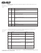
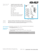


Table Of Contents

Copyright © 2011, ASSA ABLOY All rights reserved. Reproduction in whole
or in part without the express written permission of ASSA ABLOY is prohibited.
WFMN5A • PAGE 10
The RS-485 bus consists of a twisted-pair cable with a characteristic impedance of between 90 Ohm
and 120 Ohms. Maximum bus length is1000m. Depending on the EAC system, a maximum of 16 units,
including the EAC system, can be connected to the same bus.
If there is more than one Communication Hub to connect, the hubs should be connected in a daisy
chain, not as a star so that all RS485 A connectors are connected together and all RS485 B connectors
are connected together on the RS-485 bus (Fig. 5). Both ends of the RS-485 bus must be terminated.
To terminate a Communication Hub at the end of the bus, switch 8 of the DIP switch must be in the ON
position. All other Communication Hubs in the chain must have switch 8 of the DIP switch set to the OFF
position. Refer to the EAC documentation for proper termination of the bus on the EAC side.
Pull up and pull down-resistors should be enabled once bus. Refer to EAC documentation for use of
pull up or pull down on the EAC side. If pull up and pull down from the EAC system is not used, one
Communication Hub on the bus should have DIP switches 6 and 7 set to the ON position.
Two examples of connection of multiple Communication Hubs to a single RS-485 bus of an EAC system:
RS485 Bus
Connection
EAC System
Hub 1
Hub 2
Hub N
End of Bus
Termination
Enabled
DIP 6 OFF
DIP 7 OFF
DIP 8 OFF
DIP 6 OFF
DIP 7 OFF
DIP 8 OFF
DIP 6 ON
DIP 7 ON
DIP 8 ON
A
B
A B
A B
A B
DIP 6 ON
DIP 7 ON
DIP 8 ON
Termination
disabled
DIP 6 OFF
DIP 7 OFF
DIP 8 ON
Hub 1
Hub 2
A B
A B
EAC System
Figure 4. Examples, Communication Hub Connections
aDDreSSeS a0 a1 a2 a3
0 ON
1 ON
2 ON ON
3 ON
4 ON
5 ON ON
6 ON ON
7 ON ON ON
8 ON
9 ON ON
10 ON ON
11 ON ON ON
12 ON ON
13 ON ON ON
14 ON ON ON
15 ON ON ON ON
Figure 5. Address Examples