
User Manual
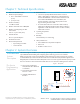
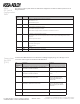
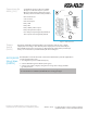

Table Of Contents

Copyright © 2011, ASSA ABLOY All rights reserved. Reproduction in whole
or in part without the express written permission of ASSA ABLOY is prohibited.
WFMN5A • PAGE 6
This section provides a quick reference to DIP switch configurations for AH20 to the EAC system at use of a
Wiegand interface.
AH20
DIP Switch
Configuration
Table
DIP SwItch
Number
LabeL DeScrIPtIoN
1 A0 Controls use of LED Red signal to deduce access decision.
ON => LED Red is used.
OFF => LED Red is ignored.
2 A1 Set to OFF by default. Reserve for futer use.
3 A2 Controls addition of parity bits if required.
ON => Addition of parity bits is enabled.
OFF => Addition of parity is disabled. Credentials are transmitted as received.
4 A3 Controls byte order of transmitted credentials.
ON => The byte order is reversed compared to what is received as input to the Hub Wiegand EAC interface
component.
OFF => The byte order is left as is.
5 Used in “Pairing Mode”.
ON => Starts in pairing mode.
OFF => Normal use.
6-9 A4 Not used.
10 INT/EXT Internal/External Antenna Use, ON = Internal
hub
coNNector
DeSIgNatIoN
DeScrIPtIoN coNNectIoN
DATA 1 Wiegand Data 1 signal. Output from Communication
Hub. Used to transmit credentials.
Connect to Wiegand Data 1 on EAC
system.
DATA 0 Wiegand Data 0 signal. Output from Communication
Hub. Used to transmit credentials.
Connect to Wiegand Data 0 on EAC
system.
RED Wiegand RED LED signal. Input to Communication Hub.
Used to deduce an access decision.
Connect to Wiegand RED LED
output on EAC system. Leave
unconnected if DIP switch 1 is
selected “OFF”.
GREEN Wiegand Green LED signal. Input to Communication
Hub. Used to deduce an access decision.
Connect to Wiegand Green LED
output on EAC system. See DIP
1 on previous page for alternate
instructions.
GND Ground Connect to EAC System ground.
8-24 VDC 8-24 VDC
Connections
for AH20
(J100)
Communication Hub hardware version AH20 has four Wiegand signals plus ground. The purpose and
connection of these signals are described in the table below.