
User Manual
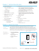
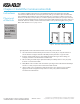
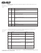
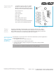

Table Of Contents

Copyright © 2011, ASSA ABLOY All rights reserved. Reproduction in whole
or in part without the express written permission of ASSA ABLOY is prohibited.
WFMN5A • PAGE 7
On the AH20 four form C relays are available.
The purpose of the four relays is to perform
Wiegand communication with an EAC System.
The relay contacts are labeled and specified as:
NCL: Normal Closed
COM: Common
NOP: Normal Open
Relay 1: DPS
Relay 2: RX
Relay 3: Battery Alarm Output
Relay 4: Tamper Alarm Output
Note: Tamper output energized by default, all
other outputs are de-energized by default.
The tamper switch will be activated if AH20 is removed from its bottom cover or plastic
adapter plate. If mounting to other than the plastic adapter plate as shown in the adapter
plate installation instructions it is necessary to align the tamper switch with a special tamper
tower post. See instructions provided with the optional mounting box.
Tamper
Switch
(AH20)
Relay Terminal Block
DIP Switch
Ground Lug
Tamper Switch
Main Terminal Block
DPS
RX
Battery
Tamper
Figure 3. AH20 Connectors
Connections for
AH20 (J103)
AH13/AH30
Integration
(RS485)
1. Set configuration options on DIP switch (S101).
2. Connect the RS485 signals to the EAC System (J100).
3. Connect to the supply voltage by wiring the 8 to 24 V (positive voltage) and GND
(ground) terminal.
The AH13/AH30 Communication Hub communicates with the EAC System through RS485. To
connect follow the below steps:
Note:
The Communication Hub must be powered with a voltage between 8 VDC and 24 VDC.
If communication is established, the LED will have a steady green light.