ASSA ABLOY, the global leader in door opening solutions MODEL DK-26 DIGITAL KEYPAD SYSTEM INSTALLATION AND OPERATING INSTRUCTIONS Securitron Magnalock Corp. Tel 800.624.5625 © Copyright, 2011, all rights reserved www.securitron.com techsupport@securitron.com PN# 500-16900 Rev.
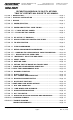
Securitron Magnalock Corp. Tel 800.624.5625 www.securitron.com techsupport@securitron.com ASSA ABLOY, the global leader in door opening solutions SECURITRON MODEL DK-26 DIGITAL KEYPAD TABLE OF CONTENTS AND GUIDE TO THIS MANUAL SECTION 1. DESCRIPTION -------------------------------------------------------------Page 2 SECTION 2. PHYSICAL INSTALLATION ----------------------------------------------Page 2 SECTION 3. WIRING --------------------------------------------------------------------Page 2 SECTION 3.
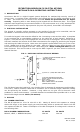
SECURITRON MODEL DK-26 DIGITAL KEYPAD INSTALLATION & OPERATING INSTRUCTIONS 1. DESCRIPTION Securitron's DK-26 is a digital keypad system designed for medium/high security control of electric locks. It consists of two components: the keypad and the CPU board connected by a 16 ft. cable. This allows the CPU board to be mounted within the protected area for higher security. Tampering with or even destroying the keypad will not release the door.
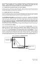
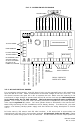
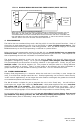
Be sure that your power source is of adequate capacity to operate both the lock and DK-26. If the installation is "under-powered", the voltage of the supply will drop rapidly when the lock is energized and this can crash the microprocessor. 3.2 CONNECTING THE KEYPAD CABLE TO THE CPU BOARD There are 12 color coded wires in the keypad cable. Refer to Figure 3 and connect each wire to the indicated terminal on the CPU Board.
FIG. 3: OVERVIEW OF CPU BOARD KEYPAD CABLE BROWN GRAY BLACK WHITE BLUE RED KEYS KEYS KEYS KEYS COMMON BEEPER RED LED GRN YEL BEIGE KEYS GRN LED ORANGE KEYS GREEN PINK KEYS YELLOW YEL LED VIOLET RED BLU WHT BLK GRY BRN BGE ORG PNK VIO PS3 PS2 PS1 AC 12/24 AC POWER MICROPROCESSOR IN SPDT RELAY DISABLE HARD CODE REX UCD HCD NCX DISABLE ALL USER CODES PUSH TO PROGRAM HARD CODE SRC REX INPUT (REMOTE RELEASE) HARD CODE COM.
the lock. DC locks operated in this way must not draw more than 2 Amps. The positive DC terminal connects to the common of relay #1 and either the NO1 terminal (if the lock is fail secure) or the NC1 terminal (if the lock is fail safe) connects to the lock’s positive power input. This is shown in dotted lines. You only connect one of these terminals. Note that some DC locks are polarized and you must connect lock power correctly to positive and negative.
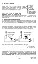
3.4 USE OF THE “F” TERMINAL AC FIRE ALARM The F terminal on the power strip is not connected to CONTACTS anything. It is a free terminal with either of two TRANSintended uses. First, on some complicated NC FORMER installations, a large number of wires (generally DC C negative) may require termination. It can be convenient to run a jumper from the DC- terminal to WHEN THE FIRE the F terminal so that the large number of negative ALARM CONTACTS returns can be spread on to the two terminals.
There are some special characteristics as to how the REX input works. First, it does not start the timer when the input is closed but rather when it reopens. This means that you can use the REX input to release the door for an extended period of time. As long as terminals REX and SRC remain connected, the lock will be released. When they disconnect, the lock will remain released for the amount of time programmed. The REX input is also retriggerable.
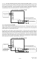
FIG. 8: DOUBLE BREAK WIRING FOR FREE EGRESS (SPDT SWITCH) AC IN NC F DC IN/OUT + C + NO CPU BOARD SPDT SWITCH REX NC1 MOV FAIL SAFE ELECTRIC LOCK C1 WHEN THE EXIT SWITCH IS ACTIVATED, THE NC CONTACTS OPEN WHICH RELEASES THE FAIL SAFE LOCK. AT THE SAME TIME, THE NO CONTACT DIRECTLY ACTIVATES THE REX INPUT. THIS DEENERGIZES THE LOCK CONTROL RELAY WHICH RELEASES THE LOCK "A SECOND TIME" FOR THE AMOUNT OF TIME THAT HAS BEEN PROGRAMMED.
Below we show a step by step summary. Power up unit; confirm steady yellow LED Press the “Hard Code” button on the CPU board for one second Confirm slow flashing yellow LED Within 30 seconds of pressing Hard Code button, enter a 2-7 digit code Wait 5 seconds Note two red LED flashes for confirmation Re-enter code (door should open) As mentioned at the beginning of this section, here is the procedure to follow if you don’t get a steady yellow light on power up.
As mentioned at the beginning of this section, here is the procedure to follow if you don’t get a steady yellow light on power up. The absence of the yellow light means that for any reason, the unit already has one or more codes in memory. You must erase these other codes to be certain that the unit will operate only on the codes you plan to enter. Follow the steps shown below. Press the “Hard Code” button on the CPU board for one second.
program additional User codes, you follow the procedures described above for setting the User code in memory location 01 but you employ memory locations 02 through 59. For example, once the unit is in program mode (rapid yellow flash), entering 0-2 followed by a code sequence will enter a second User code. The same is true when you enter prefixes 0-3, 0-4 up to 5-9. When you’re programming multiple User codes, note that you can enter them one right after another.
immediately see the two red confirmation flashes. Otherwise press the Bell key or wait five seconds. If you get the single red error flash, it is probably because the code you thought was in memory was not. You’ll then need to press the Bell key again to exit program mode or wait 30 seconds. To delete all User codes, there is a special prefix. Put the unit into program mode (fast yellow flash) from the “Prgm Code” button or from the existing Program code and enter 8-8.
6. USE OF THE PROGRAMMABLE RELAY The DK-26 CPU board includes a second relay whose 5 Amp, SPDT contacts are marked CX, NCX and NOX (see Figure 2). This relay is employed for different functions which are selected by commands sent to the CPU board while the unit is in program mode. In general, you need to choose the function you want to make active for this relay (if any) and the following sections lay out the choices. 6.
6.4 DOOR PROP ALARM FUNCTION This function provides enhanced security at the door CONNECT A DOOR SRC UCD HCD SWITCH WHICH by creating an alarm signal any time the door is left OPENS WHEN THE open too long while being used for entry or exit. DOOR OPENS TO With the function enabled, select a relatively long UCD OR HCD door open time (see Section 4.5 to set timer). You DEPENDING ON WHICH will then need a door switch whose contacts open COMMAND YOU CHOOSE when the door opens.
don’t violate egress building codes when employing a keypad on the inside of a door. Check with your local building or fire department. 7.2 HARDWIRED CODE DISABLING This means making a switch connection to the CPU board which will cause valid codes to not be accepted. The DK-26 has two terminals marked “HCD” and “UCD” which will respectively disable the Hard code and all User codes.
7.4 ANTI-TAILGATING Particularly when using the longer time ranges, the end user may be concerned that after an authorized person has used the door, a second unauthorized person can also use it before the lock has reset. By the addition of a door switch which opens when the door opens, the DK26 can be made to re-engage the lock as soon as the door has re-closed regardless of the status of the timer.
APPENDIX A: COMMAND SUMMARY WITH THE UNIT IN PROGRAM MODE (FAST YELLOW FLASH): 00 followed by 5-7 digits sets Program code 01 followed by 2-7 digits set first User code 02-followed by 2-7 digits sets second User code Additional User codes can be set up to the prefix 59 (total 59 User codes) 70 will sound beeper when door is open (except toggle mode).
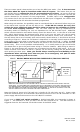
PS3 PS2 PS1 AC IN If the relay doesn’t operate when SRC and REX are connected, the CPU board has either tripped one of its automatic fuses or has some major problem requiring replacement. The DK-26 employs three special type fuses called PolySwitches. PolySwitches look like capacitors. To identify them on the board note the drawing to the right.
PROBLEM-- Keys do not operate but a beep is heard every five seconds This is a diagnostic feature which indicates that one of the keys is being read as down (always being pressed). In that condition, the CPU board will not be able to read any other keys. It can happen because of mechanical failure within the switch element such that the key really is down, or keypad wires that are shorted to each other.
come on, the problem is with the LED in the keypad or with the internal wiring within the keypad. The keypad will have to be replaced to restore operation of the LED. PROBLEM-- Error signal (one second long red pulse) received while programming Anytime you receive an error signal, retry the programming operation. It’s easy to mis-hit one key. If the error signal persists, it is almost always a misunderstanding of programming procedures rather than a fault with the unit.
noise producing devices such as motors, fluorescent or neon lighting etc. The same problem can occur if the cable from an exit switch is extended a long way from the CPU board. If there are noise sources, it may be necessary to limit the cable run distances while also trying to avoid the noise sources. If the problem shows up frequently, it is usually bad power. This particularly occurs when a fail secure lock is operated from the same supply as the DK-26.