H2 Harmony Series Mortise Lock Installation Instructions A8027G 06/17 Copyright © 2017, Sargent Manufacturing Company, an ASSA ABLOY Group company. All rights reserved. Reproduction in whole or in part without the express written permission of Sargent Manufacturing Company is prohibited.
1 2 3 4 5 6 7 8 9 1 Table of Contents Warning ....................................................................................2 General Description..................................................................3 Technical Specifications..........................................................3 Regulatory Specifications........................................................3 Parts Breakdown......................................................................4 Installation Instructions.......
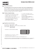
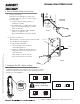
Harmony Series H2 Mortise Lock 2 General Description The SARGENT Harmony Series H2 mortise lock is designed to interface with existing Wiegand Electronic Access Control (EAC) panels. The reader requires 12 or 24VDC for power and is compatible with HID® iCLASS® 13.56MHz technology. Harmony Series technology is backed by SARGENT’s Grade 1 hardware. The mortise lock comes with Request to Exit (RX) monitoring within the lock body and operates from 12-24VDC.
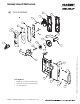
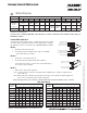
Harmony Series H2 Mortise Lock Parts Breakdown 5 7A 7B 7 5 3 2 1 1A 8 9 6 13 6 6 10 15 16 14* Tools Required: • Phillips Screw Driver (Standard size) • Slotted Screw Driver (Standard size) • 1/8" Allen Wrench A8027G • 800-810-WIRE (9473) • www.sargentlock.com 10 10 4 10 03/31/17 12 Copyright © 2017, Sargent Manufacturing Company, an ASSA ABLOY Group company. All rights reserved.
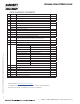
Harmony Series H2 Mortise Lock Parts Breakdown (Continued) Item Part # Description 1 52-4039 Outside Harmony Escutcheon With Cylinder Prep 1 1A 52-4040 Outside Harmony Escutcheon Without Cylinder Prep 1 2 52-0796 Outside Weather Gasket 1 3 52-0795 Inside Weather Gasket 1 5 52-5236 Screw Pack (5A; 5B; 5C; 5D) 1 6 82-4355 Trim Pack - Standard levers 1 79-2162 Trim Pack - Deco levers (shown) 7 52-4517 H2-IA-02 Controller Assembly 1 7A 52-5196 Inside Escutcheon w/ Turn Assemb
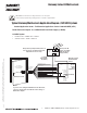
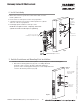
Harmony Series H2 Mortise Lock Wiring Diagrams 6 Product 8 PIN CONNECTOR 1-Black 2-Red 3-White 4-Green 5-Orange 4 PIN CONNECTOR 6-Blue 7-Brown 8-Yellow 1-Violet 2-Gray 3-Pink 4-Tan DPS (NC) DPS (COM) ACCESS CONTROL DEVICES: Harmony H2 Mortise, ElectroLynx wire Color / Function assignments SARGENT HARMONY SERIES 12/24VDC (Reader) WIEGAND WIEGAND RX RX EGND LED REF. *DIAGRAMS REF.
Harmony Series H2 Mortise Lock *IMPORTANT: Pin 7 must be tied to earth ground in the access control panel. Failure to follow proper ESD safe grounding procedures could lead to equipment failure.
Harmony Series H2 Mortise Lock 6 Installation Instructions 1 Door Preparation A. Verify Hand and Bevel of Door Stand on outside of locked door when determining door hand. Left Hand Hinges Left. Open Inward. “LH” Left Hand Reverse Bevel Hinges Left. Open Outward. “LHRB” Right Hand Hinges Right. Open Inward. “RH” Fig. 1A Right Hand Reverse Bevel Hinges Right. Open Outward. “RHRB” B. Door Preparation Prior to installation, make sure all holes are free of burrs, debris, and sharp edges.
Harmony Series H2 Mortise Lock 2 How to Change Hand of Lock body A. Reverse Lock Hand Red surface of locking piece must face the outside/locked side of door. To rotate locking piece (Fig. 2A): Right Hand Lock Shown 1. Position lock body with red surface of locking piece visible. 2. Insert blade type screwdriver into locking piece slot to rotate locking piece toward back of lock body. Locking Guide Slot: Red color indicates locked side. 3.
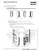
Harmony Series H2 Mortise Lock 4 Install Lock body 1. Wires and connectors go into the mortised area and out of the inside cylinder hole. Inside of Door 2. Insert mortise lock body into mortise door preparation. 3. Carefully feed wires from mortise lock through the non-cylinder side hole of the door preparation. 12 Conductor Network/Power Cable (ElectroLynx) from McKinney 4. Install appropriate hardware lock body screws. NOTE: Do not tighten screws completely at this time.
Harmony Series H2 Mortise Lock 5 Outside Escutcheon and Inside Mounting Plate Installation (Continued) 2. Feed the reader cable located on the back of the outside escutcheon through the door prep (Fig. 5B). 3. Outside gasket must be used when installing Harmony in an outdoor application (Fig. 5B). 4. Secure the mounting plate to the outside escutcheon with (2) #8-32 x 2” flat head machine screws (Fig. 5C).
Harmony Series H2 Mortise Lock 7 Outside Cylinder Installation 1. Verify orientation of cylinder so that SARGENT logo is right-side up (Fig. 8A). 2. Withdraw the key about 25% out of the cylinder before inserting into the escutcheon (Fig. 8B). 3. Use the key to rotate the cylinder clockwise until it is flush at the bottom and the SARGENT logo is right-side up. Do not attempt to tighten all the way. 4. Tighten the cylinder clamp set screw to prevent unscrewing of the cylinder (Fig. 8C). 5.
Harmony Series H2 Mortise Lock 8 Outside Lever and Inside Adapter Plate Assembly Installation 1. With outside lever horizontal, insert the mounting post through outside of door and lock body. Make certain the lever spindle is properly engaged inside the lock body (Fig. 9A). 2. On the inside of the door, insert slotted spindle into square hole of mortise lock (Fig. 9B), with spindle slot directed away from the lock body, and aligned with the set screw hole in the inside adapter. 3.
Harmony Series H2 Mortise Lock 9 Installing Controller Please follow these steps prior to installing inside escutcheon to prevent any damage caused by pinching wires: Inside of Door 1. Feed controller harness earth ground into and around behind rim of large upper hole of the mounting plate (Fig. 10A, B). Inside of Door P5 Controller PCB Fig. 10B Earth ground J5 J2 Fig. 10A 03/31/17 Copyright © 2017, Sargent Manufacturing Company, an ASSA ABLOY Group company. All rights reserved.
Harmony Series H2 Mortise Lock Install Controller Once wires are arranged, position controller at a rotated angle against the door, under earth ground wire. a. Press piece against door while turning clockwise (Fig. 11A). b. Twist into place, perpendicular with door (Fig. 11B). c. Position two-wire green/yellow ground wire ring terminal (from lock body) over hole for top left screw (Fig. 11B, C). d.
Harmony Series H2 Mortise Lock 12 Connector Attachment (Exterior PCB Assembly) 1. Connect P3 (2-pin connector) from lock body to J3 on module (Fig. 12). 2. Connect P4 (6-pin connector) from lock body to J4 on module (Fig. 12). P3 P4 13 Install Inside Escutcheon Assembly 03/31/17 Copyright © 2017, Sargent Manufacturing Company, an ASSA ABLOY Group company. All rights reserved. Reproductions in whole or in part without express written permission of Sargent Manufacturing Company is prohibited.
Harmony Series H2 Mortise Lock 14 Inside Rose and Inside Lever Assembly Instructions 1. Rotate the inside rose - first counter clock wise to seat the threads and then, clockwise to securely tighten. Inside of Door 2. Slide lever handle onto spindle until fully seated. Be sure handle is horizontal and facing the hinge side of the door. Push lever onto spindle so minimum gap is visible. 3. Tighten the set screw securely with a 1/8” hex wrench. Spindle 4.
Harmony Series H2 Mortise Lock 9 Mechanical Operational Check For 82280-82283 & 82270-82273 Function mortise locks with cylinders: 1. Insert key into cylinder and rotate: There should be no friction against lock case, wire harness or any other obstructions. 2. The key will retract the latch: Key should rotate freely. 3. When the deadbolt is thrown: Ensure that the key retracts both the deadbolt and the latch. 4. Inside lever: When used, ensure it retracts both the latch and deadbolt (if provided). 5.
SARGENT Manufacturing 100 Sargent Drive New Haven, CT 06511 USA 800-727-5477 • www.sargentlock.com Founded in the early 1800s, SARGENT® is a market leader in locksets, cylinders, door closers, exit devices, electro-mechanical products and access control systems for new construction, renovation, and replacement applications. The company’s customer base includes commercial construction, institutional, and industrial markets. Copyright © 2017, Sargent Manufacturing Company, an ASSA ABLOY Group company.