
User's Manual

03/31/17
Copyright © 2017, Sargent Manufacturing Company, an ASSA ABLOY Group company. All rights reserved.
Reproductions in whole or in part without express written permission of Sargent Manufacturing Company is prohibited.
Harmony Series H2 Mortise Lock
A8027G • 800-810-WIRE (9473) • www.sargentlock.com 10
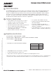
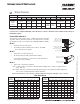
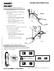
1. Wires and connectors go into the mortised area and out of the
inside cylinder hole.
2. Insert mortise lock body into mortise door preparation.
3. Carefully feed wires from mortise lock through the non-cylinder
side hole of the door preparation.
4. Install appropriate hardware lock body screws.
NOTE: Do not tighten screws completely at this time.
Cylinder should be installed prior to tightening.
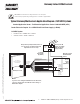
Inside of
Door
(2)#12 x 1-1/4” Long Flat Head Wood
Screws (Wood Doors)
Fig. 4
(2) #12-24 x 1/2” Long Flat
Head Philips Screws (Metal Doors)
Feed connectors
and wires through
non-cylinder side.
4 Install Lock body
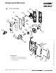
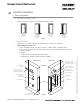
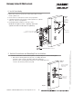
5 Outside Escutcheon and Mounting Plate Installation
NOTE: Feed mortise connectors through the corresponding hole on the mounting plate.
1. Attach the mounting plate using (2) 8-32 x 2" Phillips flat head
undercut combo screws in the upper right and middle left
positions of the mounting plate and (2) 8-32 x 3/8" Phillips flat head
screws in the bottom positions (Fig. 5A).
Fig. 5A
(2) 8-32 x 3/8” Phillips
Flat Head Undercut
Combo Screw
(2) 8-32 x 3/8”
Phillips Flat
Head Screw
Inside of
Door
12 Conductor
Network/Power
Cable
(ElectroLynx)
from McKinney