
User's Manual

03/31/17
Copyright © 2017, Sargent Manufacturing Company, an ASSA ABLOY Group company. All rights reserved.
Reproductions in whole or in part without express written permission of Sargent Manufacturing Company is prohibited.
Harmony Series H2 Mortise Lock
A8027G • 800-810-WIRE (9473) • www.sargentlock.com 6
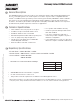
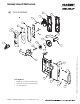
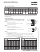
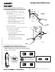
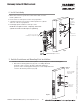
Wiring Diagrams
6
Product 8 PIN CONNECTOR 4 PIN CONNECTOR
1-Black 2-Red 3-White 4-Green 5-Orange 6-Blue 7-Brown 8-Yellow 1-Violet 2-Gray 3-Pink 4-Tan
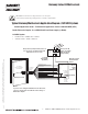
ACCESS CONTROL DEVICES: Harmony H2 Mortise, ElectroLynx wire Color / Function assignments
SARGENT -
HARMONY
SERIES
H2 Mortise
12/24VDC
(Reader)
WIE-
GAND
WIE-
GAND
RX RX EGND LED 12/24 VDC
(LOCK RELAY)
DPS
(NC)
DPS
(COM)
NEG POS DATA_1 DATA_0 NO/NC COM REF.
*DIA-
GRAMS
REF.
*DIA-
GRAMS
NEG POS DPS DPS
Bored/Exits NEG POS DATA_1 DATA_0 ?? COM NEG POS NC NC
Reader LED Configuration
The Harmony Series reader can be configured for (3) modes of LED
operation. HID Programming cards are also supported to configure
the behavior for LED color activity. Call 1-800-810-WIRE for details.
Mode 1:
• Red LED ‘ON’ when powered.
• Presenting a valid credential causes LED to ‘FLICKER’
green and return to red state.
Mode 2:
• Green LED “ON” when powered.
• No Flicker after presenting valid valid credential.
PIN 8 (Yellow – LED)
PIN 6 (Blue – RX COM)
PIN 4 (Green – Data 0)
PIN 2 (Red – Reader POS)
PIN 1 (Black – Reader NEG)
PIN 3 (White – Data 1)
PIN 5 (Orange – RX NO/NC)
PIN 7 (Brown-EGND)
PIN 4 (Tan – DPS COM)
PIN 2 (Gray – Lock POS)
PIN 1 (Violet – Lock NEG)
PIN 3 (Pink – DPS NC)
Mode 3:
• EAC Panel controls LED operation.
Note: Control of LED is a function of the EAC panel equipment (i.e. relay) to toggle between
green and red.
Note: When LED wire is tied directly into EAC panel relay, no AC signals should be applied on
wire or door reader performance will be impacted.
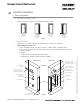
*Diagram on following page
If your lock is configured with End of Line Resistors, reference instruction sheet A8191 for the wiring of
RX & DPS outputs.
Note: LED wire must be connected to circuit GROUND of
the system’s power supply.
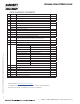
Total
One-Way
Length of
Wire Run (ft)
Load Current @ 12VDC
1/4A 1/2A 3/4A 1A 1-1/4A 1-1/2A 2A 3A
100 20 18 16 14 14 12 12 10
150 18 16 14 12 12 12 10 —
200 16 14 12 12 10 10 — —
250 16 14 12 10 10 10 — —
300 16 12 12 10 10 — — —
400 14 12 10 — — — — —
500 14 10 10 — — — — —
750 12 10 — — — — — —
1,000 10 — — — — — — —
1,500 10 — — — — — — —
Wire Gauge Charts
Total
One-Way
Length of
Wire Run (ft)
Load Current @ 24VDC
1/4A 1/2A 3/4A 1A 1-1/4A 1-1/2A 2A 3A
100 24 20 18 18 16 16 14 12
150 22 18 16 16 14 14 12 10
200 20 18 16 14 14 12 12 10
250 18 16 14 14 12 12 12 10
300 18 16 14 12 12 12 10 —
400 18 14 12 12 10 10 — —
500 16 14 12 10 10 — — —
750 14 12 10 10 — — — —
1,000 14 10 10 — — — — —
1,500 12 10 — — — — — —
Wire from EAC panel to door must be shielded with drain terminated at EAC panel controller