
User's Manual

Copyright © 2017, Sargent Manufacturing Company, an ASSA ABLOY Group company. All rights reserved.
Reproductions in whole or in part without express written permission of Sargent Manufacturing Company is prohibited.
03/31/17
Harmony Series H2 Mortise Lock
A8027G • 800-810-WIRE (9473) • www.sargentlock.com7
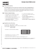
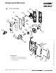
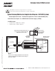
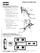
Typical Harmony Mortise Lock Application Diagram (12/24VDC System)
12 Conductor
ElectroLynx Harness
From McKinney
Harmony Series H2
Standard Application Shown - For Alternative Applications Contact 1-800-810-WIRE (9473)
Harmony Series H2
Requires 12 or 24VDC
UL294 Listed Power
Supply (or UL603)
120 VAC
Input
12/24VDC
H N G
- +
Black (Hot)
White (Neutral)
Green (Gnd)
(-)
12/24VDC
(+)
DATA 1
DATA 0
RX
RX
Electronic
Access
Control
Panel
(By Others)
Use (NC) for
Fail Safe
Operation
Lock Relay
(NO) Fail
Secure
Operation
DPS
DPS
Not Used
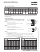
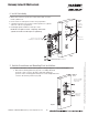
READER NEG - Black, 1
READER POS - Red, 2
DATA 1 - White, 3
DATA 0 - Green, 4
RX (NO/NC) - Orange, 5
RX (COM) - Blue, 6
*EGND- Brown, 7
LED - Yellow, 8
LOCK NEG - Violet, 9
LOCK POS - Gray, 10
DPS (NC) - Pink, 11
DPS (COM) - Tan, 12
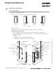
QC12 Electric
Hinge From
McKinney
Lock body
Power Supply
(By Others)
Reader Electronics Require 12 or 24VDC UL294 Listed Power Supply (or UL603)
This product is polarity sensitive; if the lock
does not operate, check the polarity of the
input and reverse if necessary.
12/24VDC System
• Reader Draw = 150mA @12 or 24VDC
• Actuator Draw = 15mA continuous
NOTE:
If your lock is configured with End of Line Resistors,
reference instruction sheet A8191 for the wiring of
RX & DPS outputs.
Harmony Series H2
UL294 Listed EAC
Product
*IMPORTANT: Pin 7 must be tied to earth ground in the access control panel.
Failure to follow proper ESD safe grounding procedures could lead to equipment failure.