
User's Manual

Copyright © 2017, Sargent Manufacturing Company, an ASSA ABLOY Group company. All rights reserved.
Reproductions in whole or in part without express written permission of Sargent Manufacturing Company is prohibited.
03/31/17
Harmony Series H2 Mortise Lock
A8027G • 800-810-WIRE (9473) • www.sargentlock.com9
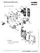
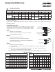
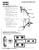
Red surface of locking piece must face the
outside/locked side of door. To rotate locking
piece (Fig. 2A):
1. Position lock body with red surface of
locking piece visible.
2. Insert blade type screwdriver into locking
piece slot to rotate locking piece toward
back of lock body.
3. Rotate the locking piece 180° until RED
surface is on opposite side.
Note: Red indicates locked side (outside).
Beveled surface of latch must face strike (Fig. 2B).
The deadlatch is self adjusting.
To change hand of latchbolt:
1. Insert screwdriver into the spade-
shaped (triangular) slot.
2. Rotate screwdriver 90º to push latch out
until back of latch clears lock front; then
rotate latch 180º.
Latch will then re-enter lock body.
Note: Latch cannot be unscrewed.
Fig. 2A
Locking Guide Slot:
Red color indicates
locked side.
Push In
Right Hand
Lock Shown
2 How to Change Hand of Lock body
A. Reverse Lock Hand
B. Reverse Latch Hand
Triangular Slot
Latchbolt
Fig. 2B
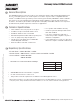
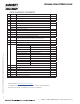
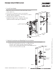
3 Configure the DIP Switch Settings
DIP Switch
1 2 3
Handing
RH & RHR
LH & LHR
Actuator Operation
Fail Safe
Fail Secure
RX Output
Normally
Open
Normally
Closed
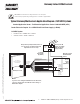
Check Polarity:
Verify + (red wire)
IMPORTANT: This product is built and factory tested to the
configuration specified. Any change to the 3-position DIP-switch
settings located at the bottom of the mortise lock body must be
made prior to lock installation.