
User Manual
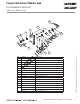
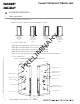


Table Of Contents

12/15/10
1-800-810-WIRE • www.sargentlock.com • A8011E 13
Copyright © 2010, Sargent Manufacturing Company, an ASSA ABLOY Group company. All rights reserved.
Reproductions in whole or in part without express written permission of Sargent Manufacturing Company is prohibited.
Passport 1000 Series P2 Mortise Lock
9
Install Inside Module Component Assembly
Insert bottom of Module Component Assembly first (Fig.
9A), then clip top of Assembly to backplate, verifying
both tabs attached securely.
Outside of Door
Fig. 9A
Tabs
10
Attach Connectors
Secure the following connectors onto the circuit board (Fig.
10A and 10B):
1. Secure the 10-pin lock body assembly connector.
2. Secure the 24-pin keypad/card reader connector.
3. Secure 9-pin reader cable (iCLASS only).
Notes:
• Connectors go on only one way.
• Do not force and do not offset connectors.
• Be sure the connectors are completely seated (flush).
Fig. 10A
Detail 10B
24-pin from
Outside Trim
10-pin from
Lockbody
Fig. 10B Detail
9-pin Reader Cable
(iCLASS Only)
PRELIMINARY