
User's Manual


8
IN100 Cylindrical Lock
Copyright © 2016 Corbin Russwin, Inc., an ASSA ABLOY Group company.
All rights reserved. Reproduction in whole or in part without the
express written permission of Corbin Russwin, Inc. is prohibited.
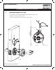
5) Installation Instructions (Continued)
Fig. 6a
Fig. 6b
Outside Face of Door
6
a. Feed lock body and wire through 2-1/8” diameter hole from outside of door (Fig. 6a).
Engage latch with lock body. Latch ears must slide into housing as shown (Fig. 6b).
6. Install Lock Body
Fig. 6c
Inside Face of Door
Spring Cassette
b. Connect 4-pin connector from lock body to 4-pin on
cassette (Fig. 6c).
c. Temporarily install top throughbolt to hold chassis in door (Fig. 6c).
Important: Door must remain open during installation.
Use door stop.
d. Connect REX wire from I/S cassette to
lockbody harness.