
User's Manual


07/31/16
1-800-810-WIRE • www.sargentlock.com • A8190B 9
Copyright © 2016, Sargent Manufacturing Company, an ASSA ABLOY Group company. All rights reserved.
Reproductions in whole or in part without express written permission of Sargent Manufacturing Company is prohibited.
IN100 Mortise Lock
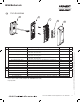
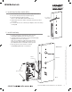
5 Install Lock body
1. Feed the wire harness through the mortise pocket
and inside preparation hole as shown in Fig. 5.
2. Carefully push the lock body into the pocket while lightly
applying tension to the wire harness.
Note: Do not pull the lock into the pocket with the
harness alone. Ensure that the wire harness is not
pinched between the lock and the mortise pocket.
3. Insert (2) #12-24 screws into the lock body
and partially tighten with a screw driver.
Mortise
Connectors
Fig. 5
Outside of Door
(2) #12-24 screws
Wire Hole
Ground Wire
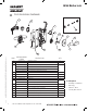
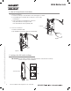
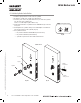
4 Install Door Position Switch (DPS)
1. Insert DPS into the raceway on the latch edge of the door.
2. Push wires through raceway toward lock prep.
3. Push DPS firmly into place by hand.
Note: DO NOT TAP SWITCH WITH ANY TOOL.
4. Install magnet into door frame. Push firmly into place by hand.
See A7983.
5. To connect DPS to lock controller per diagram, refer to the wiring
in Step #10.
Fig. 4
Door Position
Switch (DPS)