
User Manual
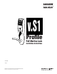


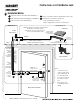
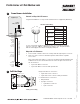

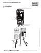

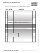
Table Of Contents

01/29/11
1-800-810-WIRE • www.sargentlock.com • A7764B 5
Copyright © 2011, Sargent Manufacturing Company, an ASSA ABLOY Group company. All rights reserved.
Reproductions in whole or in part without express written permission of Sargent Manufacturing Company is prohibited.
Profile Series v.S1 PoE Mortise Lock
A
Frame Harness Installation
Suggested installation of components and wire harness supplied by McKinney:
RJ45-M
Molex-M
Cable: CAT 5e or higher
24 AWG shielded, 100ohm
B-Splice
Crimp Connector
Ceiling
Supplied by CI
Cut end / ceiling-side PoE harness:
TIA-568-B Standard Wiring
1
2
3
4
5
6
7
8
Pair Number Wire PIN
1 White/Blue
White/Blue 5
Blue 4
2 White/Orange
White/Orange 1
Orange 2
3 White/Green
White/Green 3
Green 6
4 White/Brown
White/Brown 7
Brown 8
Do not confuse pair numbers with pin numbers. A pair number is used for
reference only (e.g.: 10Base-T Ethernet uses pairs 2 & 3). The pin numbers
indicate actual physical locations on the plug and jack.
1. Feed cut end of harness into hole on hinge-side through single access hole.
2. Push one of the connectors back through hole and feed into separate
access hole.
Hinge side of PoE harness:
B
Each of the hinge-side harness connectors should end up threaded through
a different access hole and matched to the same size pin connector from
the door harness:
• 4-pin male Molex connector.
• 6-pin male Molex connector with ground wire.
Frame-Side
Harness
Assembly
(15' length)
24AWG
Stranded
Wire for
Earth
Ground
inside
15' Frame
Harness
Cable
drain wire
concealed
in shrink
tubing
6-pin F
4-pin M
6-pin M
4-pin F
Drain Wire
Frame PoE Hinge (Patent Pending)
PoE Data Hinge
Hinge-side harness connectors:
• 4-pin male molex connector
• 6-pin male molex connector with ground wire
Lock-side harness connectors:
• Ring terminal
• (2) 4-pin connectors
• 4-pin Molex connector
• 4-pin connector
B