
User Manual


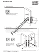
Table Of Contents

8/05/12
1-800-810-WIRE • www.sargentlock.com • A8122B 9
Copyright © 2012, Sargent Manufacturing Company, an ASSA ABLOY Group company. All rights reserved.
Reproductions in whole or in part without express written permission of Sargent Manufacturing Company is prohibited.
IN100 Mortise Lock
6
Attach Front Plate
Attach front plate with (2) flat head screws.
Outside of Door
Fig. 6
(2) flat head screws
Scan this Microsoft® Tag using your mobile phone
to see a video of this installation step. The Microsoft
Tag mobile app is required to scan the Tag.
Download the free mobile app at http://gettag.mobi
7 Assemble Trim
1. With outside lever horizontal, insert the mounting post through outside of door and lock body.
Make certain the lever spindle is properly engaged inside the lock body (Fig 7A).
2. On the inside of the door, insert spindle into square hole of mortise lock (Fig 7B).
3. Slide inside adapter and plate assembly over spindle and secure with (2) 8-32 X 5/8” Phillips
oval head and lock washer machine screws.
Fig. 7B
Fig. 7A
8-32 X 5/8”
Phillips
Oval
Head and
Lock
Washer
Machine
Screw
Inside of DoorOutside of Door
Outside Trim
Scan this Microsoft® Tag using your
mobile phone to see a video of this
installation step. The Microsoft Tag
mobile app is required to scan the
Tag. Download the free mobile app at
http://gettag.mobi
Assemble Trim
Inside Lever
Assembly
Preliminary