
Installation & Assembly

4of7
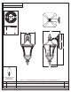
Figure 4
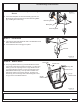
STEP 4 Attach Lanyard-
A. The purpose of the lanyard is to provide the installer a
means to support the fixture from the junction box while
connecting the electrical wires. This enables the fixture
to hang from the junction box and your hands are free to
make the wire connections.
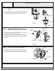
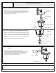
B. TurntheButtonStopsoitmaybeinsertedintothe
crossbar slot. Make sure the Button Stop is completely
inside the crossbar. Slowly release the fixture to make
sure it is supported by the Button Stop. Proceed to the
wiring steps. Once you are complete with the wiring
there is nothing to do with Lanyard. The Lanyard will
push into the junction box when the fixture is placed for
final mounting.
Crossbar
Slot
Button Stop
Lanyard
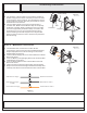
Figure 5
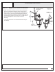
STEP 5 Make Wire Connections-
A. Use standard wire connectors to make all wire
connections. (Connectors are not included with fixture.)
Strip and prepare wire ends according to instructions
supplied with connectors.
B. Connect White Supply Wire from the Outlet Box to White
Wire from fixture.
C. Connect Black (or Red) Supply Wire from the Outlet Box
to Black Wire from fixture.
D. Connect Ground Wire from the Outlet Box to Ground
Wire from fixture.
E. Twist connectors until wires are tightly joined together.
F. Wrap each connection with approved electrical tape and
carefully stuff all the connected wires into the Outlet Box.
Figure 6
White wire from supply White wire from fixture
Black wire from supply
(or Red)
Black wire from fixture
Ground wire from supply Ground wire from fixture
Assembly Instruction