
Operating instructions


Inst.241a Viron Series Pool & Spa Heater V08.11
11
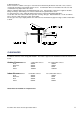
6/ Wall terminations.
Ensure location is suitable as flue gases exit all around cowl and may blow back onto walls, eaves, features
causing discolouration or mould and moisture issues. Condensation will occur around the flue exit area and
condensation may drip from the flue outlet.
All flues exiting the wall must be shielded with the gal cover. Extra lengths of gal can be supplied. Decktite
fittings / flashings / wall exiting covers must be attached to the galvanised flue cover.
For long extensions of flue exiting the wall bracing may be required in high wind applications.
Locate flue cowl onto reduced end of the gal outer covering / flue pipe. Attach with rivets / screws to hold into
place. Ensure a drain hole in the cowl is facing down.
The flue pipe must slope slightly towards the cowl for the last horizontal run (approx 2 deg) to allow condensation
to drain.
CLEARANCES
Installation clearances must comply with AS5601. The heater is approved for installation at reduced clearances as
below.
Outdoor Clearances from combustible surfaces non combustible surfaces
Front
300mm
300mm
Both sides
300mm
300mm
Rear
300mm
50mm
Above
1000mm
1000mm
Indoor Clearances from combustible surfaces non combustible surfaces
Front
300mm
300mm
Both sides
300mm
50mm
Rear
300mm
50mm
Above
500mm
500mm
Heater must be installed on a fireproof base.