
Operating instructions


Inst.241a Viron Series Pool & Spa Heater V08.11
13
ELECTRICAL CONNECTION
The heater is supplied with a standard 10 amp 3 pin plug for connection to a 240V 10 amp GPO. All pool or spa
equipment connected to mains power should be protected by an RCD circuit breaker.
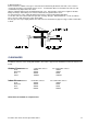
GAS CONNECTION
250/350/450 models.
The gas connection is on the rear of the heater. A 22mm M.I. connection is provided for gas line connection. An
approved manual shut off valve must be installed in the gas fitting line before the heater.
550 models.
The gas connection is on the RH side of the heater behind the lift off access panel. A 25mm compression
connection is provided for gas line connection. An approved manual shut off valve must be installed in the gas
fitting line before the heater.
The gas fitting line should be installed by an authorised person and comply with local regulations and Australian
Standard code AS5601. The gas line from the meter will usually be of a larger size than the gas inlet connection.
The heater gas valve has a built in pressure regulator and ⅛” pressure test point. On starting the heater, a
manometer must be used and the supply inlet pressure checked while the heater is running against the heater
data plate. Incorrect inlet pressures may void warranty and may result in service charges, should service be
required. Gas valves are preset and should only be adjusted by trained Astral Pool technicians.
PRESSURE SWITCH ADJUSTMENT
The Viron Pool Heater incorporates a water pressure switch which allows the burner to operate only when the
circulating pump is operating. The pressure switch is designed to operate with the heater installed up to 3 metres
above or below the surface level of the pool or spa.
It is imperative that the following be undertaken by the person who is commissioning (first starting) your pool or
spa heater. On initial start up of the heater it may be necessary to adjust the water pressure activation switch.
This switch is located behind the top right hand side panel and is screwed into the water manifold. The pressure
switch is a safety device, designed to allow operation of the heater only when the circulating pump is on and there
is sufficient water flow through the heater. It must shut the heater down immediately the pump is switched off.
To check the operation of the switch:
1. Connect the heater to mains power supply and turn power on. The thermostat should not yet display “θ”.
2. Turn on pump. The thermostat should now display “θ”.
3. Turn pump off. The thermostat should no longer display “θ”.
4. If display does not respond in this way, adjust the pressure switch as detailed below. If display responds
correctly, perform a final check with the heater operating.- See the section below titled “Starting the heater”