
Operating instructions


Inst.241a Viron Series Pool & Spa Heater V08.11
14
To adjust pressure switch:
1. Connect the heater to mains power supply and turn heater thermostat to “OFF”.
2. Turn pump on.
3. View display of heater to confirm the “θ” has appeared on the LCD display on front of heater.
4. If no symbol is present, slide toggle up to allow adjustment, then rotate knurled wheel anti clockwise (as
viewed from above) until “θ” is displayed.
5. Switch off pump.
6. View LCD display to confirm “θ”has disappeared.
7. If “θ” symbol is present when pump is OFF or “θ” does not disappear within 1 (one) second of pump
turning off, the pressure switch must be adjusted.
8. With Pump turned OFF, turn knurled wheel clockwise to increase the pressure required to activate the
switch.
9. Repeat steps 2 to 8 until symbol appears and disappears when pump turns on and off.
10. When the switch is correctly set, slide the toggle down to lock the knurled wheel in position.
11. If pressure switch cannot be made to activate heater when pump is turned on and off, a flow switch may
need to be purchased and fitted. Contact your local Astral Pool office for details.
WARNING: If the pressure switch cannot be adjusted correctly, DO NOT OPERATE THE HEATER, contact Astral
or an Authorised Service Agent for advice.
1. Perform a final check with the heater operating.- See the section below titled “Starting the heater”.
It is imperative that the heater is installed so that it does not operate when the circulating pump stops.
Recommended methods to achieve this are:
a. Correct adjustment of internal pressure switch. Ensure heater does not turn on two or three minutes after
circulating pump is turned off.
b. Installation of an external flow switch may be preferred under certain installations where internal pressure
switch does not turn heater off when circulator stops.
TESTING INLET PRESSURE
1. Note – gas pressure must be measured when unit is operating.
2. Set thermostat to “OFF”.
3. Remove top cover (2 screws at rear of heater, remove L/H side panel, remove front 2 screws hidden
inside side panel area)
4. Remove electrical enclosure screws and hinge cover forward.
5. Loosen screw from ⅛” brass test point located on inlet side of gas valve
6. Connect manometer tube to test point
7. Set thermostat to “ON” and wait for burner to ignite
8. Once burner has ignited, the manometer must indicate the nominal inlet pressure listed below.
9. Adjust inline pressure to meet minimum required pressure at main gas regulator. Do not adjust gas valve
settings..
10. Tighten test point screw.
11. Refit covers.
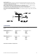
Pressure Switch Adjustment
Slide toggle
up to allow
adjustment
Turn wheel in
direction of
arrow to
decrease
pressure
required to
operate heater